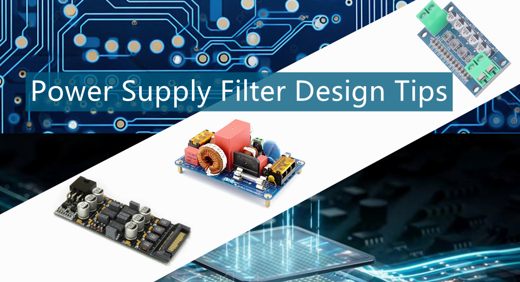
What is the purpose of using a filter in a circuit?A filter is a circuit capable of passing certain frequencies while attenuating (to reduce or block) other frequencies. Thus, a filter can extract important frequencies from signals that also contain undesirable or irrelevant frequencies. In the field of electronics, there are many practical applications for filters.Today qihe smt pick and place machine sharing some SMD Power Supply Filter Design Tips .
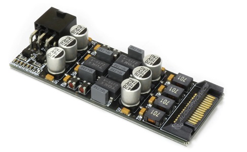
The purpose of the power supply filter is to suppress electromagnetic noise. The effects of noise can be divided into the following two types:
Emissions: It is necessary to reduce the noise generated by equipment and affecting power supplies or other equipment below the allowable value of regulations (such as FCC part 15), such as the noise generated by switching power supplies.
Immunity: It is to reduce the noise entering the equipment to a level that will not cause the equipment to operate abnormally, such as instruments used in broadcast station transmitting equipment.
Power filter installation
A. There must be no electromagnetic coupling path in the power supply filter.
①The power input cord is too long;
②The input line and output line of the power filter are too close.
Both of these are incorrect installation methods. The essence of the problem is that there is an obvious electromagnetic coupling path between the input wire of the filter and its output wire. In this way, the EMI signal existing at one end of the filter will escape its suppression by the filter and be directly coupled to the other end of the filter without being attenuated by the filter. Therefore, the filter input and output need to be effectively separated first.
In addition, if the above two types of power filters are installed inside the equipment shield, the EMI signals on the internal circuits and components of the equipment will be directly coupled to the outside of the equipment due to radiation generated on the (power) end leads of the filter. Therefore, the equipment shielding loses the ability to suppress EMI radiation generated by internal components and circuits. Of course, if there is an EMI signal on the filter (power supply), it will also be coupled to the components and circuits inside the device due to radiation, thereby destroying the suppression effect of the filter and shielding on the EMI signal. So it doesn’t work.
B.Do not bundle cables together
Generally speaking, when installing a power filter in an electronic device or system, you should pay attention to the fact that when bundling equipment cables, you must not bundle the wires at the (power) end and (load) end of the filter together, because this will undoubtedly aggravate the situation. The electromagnetic coupling between the input and output ends of the filter is eliminated, seriously damaging the ability of the filter and equipment shielding to suppress EMI signals.
C.Try to avoid using long grounding wires
The length of the wiring connecting the output end of the power filter to the inverter or motor should not exceed 30 cm.
Because an excessively long ground wire means a significant increase in ground inductance and resistance, it will seriously damage the filter’s common-mode suppression capability. A better method is to use metal screws and star-shaped spring washers to securely fasten the filter shield to the chassis at the power inlet of the equipment.
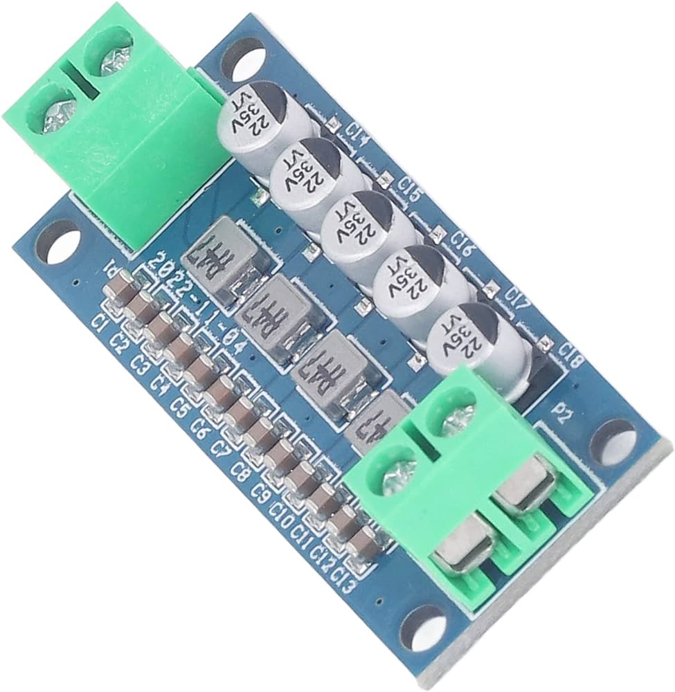
D.The input and output lines of the power filter must be kept apart.
The input and output lines of the power filter must be kept apart and should not be parallel to avoid reducing the filter efficiency.
E.The power filter shell and the chassis shell must be in good contact
The metal shell of the special filter for the frequency converter and the chassis shell must ensure good surface contact, and the grounding wire must be connected well.
F.The connection line of the power filter should be twisted pair.
It is better to use shielded twisted pair cables for the input and output connecting lines of the power filter, which can effectively eliminate some high-frequency interference signals.
Power filter parameters
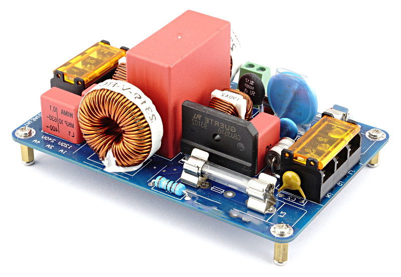
The power filter is a passive device composed of filter inductors and capacitors. It allows power frequencies (50Hz, 60Hz, 400Hz) to pass through, while greatly attenuating electromagnetic interference signals. The power supply filter is bidirectionally reversible, which can not only prevent electromagnetic interference on the power grid from entering the equipment through the power supply, but also prevent electromagnetic interference generated by the equipment itself from polluting the power grid. It is an effective configuration to suppress conducted interference.
Insertion loss
Insertion loss is an important technical indicator of the filter. In a test system where the signal source output impedance and receiver impedance are both 50Ω, the signal source output voltage is U1 when the filter is not connected. When the filter is connected, the signal source voltage measured at the filter output is U2, then the insertion loss of the filter is: Il=20log (U1/U2). Since there are two types of interference: common mode interference and differential mode interference, insertion loss is divided into common mode insertion loss and differential mode insertion loss, which represent the ability to suppress common mode noise and differential mode noise respectively.
Leakage current
Leakage current (only meaningful for AC power line filters): Under rated AC voltage, the current from the filter housing to either end of the AC incoming line. Its value mainly depends on the leakage current of the common mode capacitor Cy. Depending on the use environment of the filter, various safety standards have different regulations on leakage current, with typical values ranging from 0.5 to 5.0mA.
Withstand voltage test method
According to the national standard: the voltage starts from zero, slowly increases to the test voltage at a speed of no more than 150V/s, lasts for 1 minute, and then slowly drops to zero. Application methods include between the filter lead-out terminals and between the lead-out terminals and the filter metal shell.
Read more: SMD Power Supply Filter Design Tipspick and place machine
Best seller SMT Machine :Qihe smt line products
-
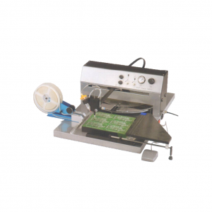
SMT semi-automatic pick and place machine with Dispenser
-
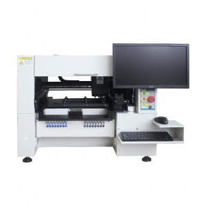
TVM925 SMT pick and place machine 4 head 38 feeders slots assembly of electronic components
-
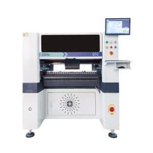
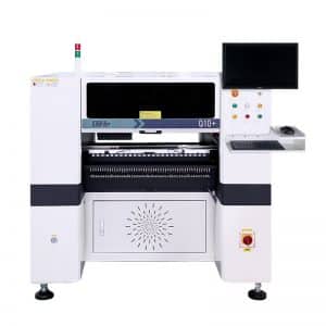
Q10 SMT Automatic pick and place machine 10 Heads 100 Slots High Precision and High Efficiency SMT/LED Assembly
-
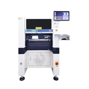
Q6 SMT pick and place machine 6heads 50slots With PCB Rail Servo Pick&Place Machine
-
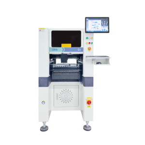
Q4 SMT pick and place machine 4heads 50slots With PCB Rail Servo Pick&Place Machine
-
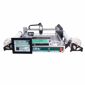
TVM802B Plus SMT pick and place machine 2heads 58slots desktop pick&place deluxe edition
-
QM10 SMT pick and place machine 10heads 80slots Fully Automatic Chip mounter SMT Assembly
-
TVM802BX SMT pick and place machine 2heads 46slots desktop pnp mounter deluxe edition
-
QL41 SMT pick and place machine 4heads 8slots LED for 1.2meters led strip pick&place machine
What is SMT in engineering?
Surface mount technology is a part of the electronic assembly that deals with the mounting of electronic components to the surface of a PCB. Electronic components mounted this way are called surface-mounted devices (SMD). SMT was developed to minimize manufacturing costs while making efficient use of board space.Qihe SMT company develops and produces all kinds of SMT equipment suitable for world wide market, including pnp machine,reflow oven,stencil printer,pcb handling machines,and other products.
Small desktop pick and place machine TVM802A,TVM802B,TVM802AX,TVM802BX series suitable for beginners, for hobbiest or low vol usag.
Advanced level 4-head LED strip placement QL41 led machines and with rail universal series TVM925S,TVM926S,pick and place
Fully automatic 6-10-head placement QM61,QM62,QM81,QM10,machines, which are suitable for high volume mass production in factories.
Know more about us https://www.qhsmt.com/about-qihe-smt-equipment/
Follow us on social media https://www.facebook.com/Qihesmt/
What is SMT in programming?
Offline Automated Programming vs Inline SMT Programming
Qihe pick and place machine can be programmed directly on the SMT equipment .
Or Coordinates can also be imported csv file through programming software.
Currently supported software such as protel,DXP,Altium Designer,Pads,Candes,proteus,DXP.
Inline SMT programming is a solution to consider for narrow segments of device programming requiring short programming times, with medium to high volume, for just one device type.
WHAT IS SMT pick and place machine?
SMT (Surface Mounted Technology) is a comprehensive system engineering technology, which covers substrates, design, equipment, components, assembly processes, production accessories and management. When it comes to SMT pick and place machines, the automatic SMT production line requires automatic loading and unloading machine, automatic solder paste printing machine, placement machine, reflow soldering machine, AOI inspection equipment, conveyor,connecting table, etc. For these SMT assembly line equipment, Qihe SMT can offer you machines in prototype SMT line, small SMT production line, mass production SMT line at low SMT line cost. Contact us now if you are interested.pick and place.pick and place machines,smt machine price,smt machine supplier,suction nozzle,smt assembly,feeder,stock in eu,pcb printer,openpnp feeder,openpnp,pcb pick and place,smt nozzle,smt line,smt meaning,smt process,smt setup,pnp machine,pcb assembly,p&p machine,p&p,pick&place,pick&place machine,pnp,stencil printer,reflow oven,pick and place machine,SMT equipment,smd machine,smt machine,SMT pick and place machine,pick and place machine,smt pick and place.
WHAT IS SMT ASSEMBLY LINE?
With the development of technology, future electronic products will be lighter, smaller and thinner. Traditional assembly technology can no longer meet the requirements of high-precision and high-density assembly. A new type of PCB assembly technology-SMT (Surface Mount Technology) has emerged. SMT Assembly is the use of automated machines to assemble electronic components on the surface of the circuit board. Its density, high speed, standardization and other characteristics occupies an absolute advantage in the field of circuit assembly technology. In addition, SMT assembly has a wide range of uses.
https://www.qhsmt.com/fully-automatic-smt-pick-and-place-machine-line/

