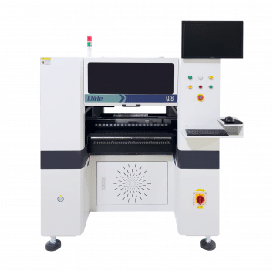
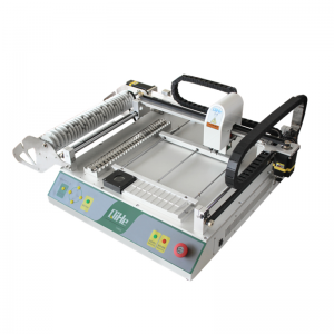
Power electronics is the technology associated with the efficient conversion, control and conditioning of electric power by static means from its available input form into the desired electrical output form.Today qihe smt pick and place machine sharing Most Asked Power Electronics supply Questions and answers.
- How to start with feedback loop design and compensation?
Smt pick and place Expert answer: The gain of the feedback loop is neither bigger nor better, nor smaller is better. When the gain of the feedback loop is too high, the output voltage will fluctuate around the average value. The higher the gain, the greater the amplitude of the fluctuation. In severe cases, oscillation will occur; when the gain of the feedback loop is too low, the output voltage will fluctuate. will be unstable. In order to stabilize the output voltage without oscillation, the feedback loop is generally divided into three loops. One loop is used to determine the size of the differential gain, the other loop is used to determine the size of the integral gain, and the third loop is Determine the size of the DC gain. By carefully adjusting the gains of these three feedback loops, the switching power supply can be stable without oscillation.
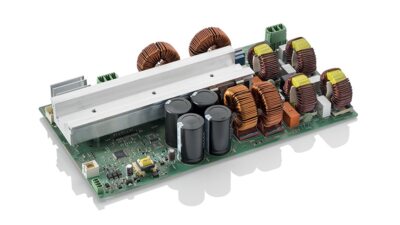
- The efficiency of DC TO DC is a bit low recently. How to solve it?
Smt pick and place Expert answer: Reduce the operating frequency, or replace the power switch tube with a high-speed switching tube. In addition, you can increase the size of the transformer and reduce the value of the maximum magnetic flux density (Bm), that is, change the primary coil of the switching transformer. The number of turns increases because the hysteresis losses and eddy current losses of the switching transformer are proportional to the operating frequency and proportional to the square of the maximum flux density increment.
- How do you calculate the minimum DC voltage? I looked at several versions but couldn’t find the one that suited me best.
Expert answer: I don’t quite understand what you mean by “minimum DC voltage” here? If it is the minimum input DC voltage of the switching power supply, it can generally be calculated based on the minimum input AC voltage. For example, if the minimum input AC voltage is AC100V (effective value), then the converted minimum DC input voltage is approximately 120V (average value). Because the maximum value after rectification and filtering is 140V, the minimum value is 100V, and the average value is 120V.
If the minimum DC voltage is the positive feedback voltage of a transistor self-excited switching power supply, then this voltage is best selected to be 2 times the operating voltage when the transistor is turned on, leaving 1 times as an adjustable margin. If the minimum DC voltage is the minimum operating voltage of the field effect transistor drive circuit, the minimum operating voltage cannot be less than 16V, because the driving voltage required for deep saturation of high-power field effect transistors is above 12V (preferably 20V).
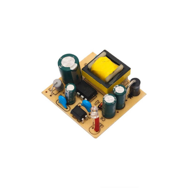
- There are burrs on the output side of the flyback transformer power supply I made, and the frequency of the burrs is the same as the switching frequency of the primary side. How can I eliminate the burrs?
Smt pick and place Expert answer: A small inductor is connected in series between the secondary rectifier and the filter capacitor, but the inductor cannot be saturated when DC flows through it. The magnetic circuit of this inductor cannot be closed, and a large air gap must be left.
- How to optimize the switching frequency of flyback power supply? How to optimize the setting of VOR flyback voltage, and under what circumstances is it most suitable? Thanks! How to optimize the turns ratio calculation? Thanks.
Smt pick and place Expert answer: The selection of the operating frequency of the flyback switching power supply is mainly related to the working efficiency and size of the switching power supply, and the working efficiency of the switching power supply is mainly related to the losses (hysteresis loss and eddy current loss) of the switching power supply tube and switching transformer. , the losses of both are proportional to frequency. The loss of the switching power supply tube is mainly composed of turn-on loss (on-time loss) and turn-off loss (off-time loss). The longer the on-time and off-time of the switching power supply tube, the greater these two losses are.
Generally, the on-time and off-time of high-power switching power supply tubes are much longer than those of low-power switching power supply tubes, so the operating frequency of high-power switching power supplies is generally lower. When considering the working efficiency of the switching power supply, considering the size and cost of the switching power supply, it is better to choose an operating efficiency of about 80%. At this time, the loss of the switching power supply tube accounts for about 50% of the total loss. The loss of the switching transformer accounts for approximately 30% of the total loss, and the loss of the remaining circuits accounts for approximately 20% of the total loss. The turns ratio of the switching transformer is related to the ratio of the input and output voltages, and to the duty cycle of the switching power supply.
- How to set the initial peak current IP and flyback voltage VOR as well as the optimal flyback power supply duty cycle, thank you!
Smt pick and place Expert answer: The magnitude of the flyback voltage generated by the primary and secondary coils of the flyback switching power supply is related to the duty cycle of the switching power supply and the input voltage. When selecting the duty cycle of the switching power supply, it must be considered. The sum of the peak value of the flyback voltage generated by the primary and secondary coils and the operating voltage (input voltage) cannot exceed 0.7 times the withstand voltage Bvmax of the power switch tube. According to this condition (Bvmax), the maximum input voltage of the flyback switching power supply can be calculated The maximum duty cycle Dmax. For example, for a power switch with a Bvmax of 650V, when the input voltage is AC260V, its duty cycle can only be selected to be about 0.306.
- How to optimize the switching frequency of flyback power supply? How to optimize the setting of VOR flyback voltage, and under what circumstances is it most suitable? Thanks! How to optimize the turns ratio calculation?
Smt pick and place Expert answer: The selection of the operating frequency of the flyback switching power supply is mainly related to the working efficiency of the switching power supply, and the working efficiency of the switching power supply is mainly related to the losses (hysteresis loss and eddy current loss) of the switching power supply tube and switching transformer. Both losses are proportional to frequency. The loss of the switching power supply tube is mainly composed of turn-on loss (on-time loss) and turn-off loss (off-time loss). The longer the on-time and off-time of the switching power supply tube, the greater these two losses are.
Generally, the on-time and off-time of high-power switching power supply tubes are much longer than those of low-power switching power supply tubes, so the operating frequency of high-power switching power supplies is generally lower. When considering the working efficiency of the switching power supply, considering the size and cost of the switching power supply, it is better to choose an operating efficiency of about 80%. At this time, the loss of the switching power supply tube accounts for about 50% of the total loss. The loss of the switching transformer accounts for approximately 30% of the total loss, and the loss of the remaining circuits accounts for approximately 20% of the total loss. The turns ratio of the switching transformer is related to the ratio of the input and output voltages, and to the duty cycle of the switching power supply.
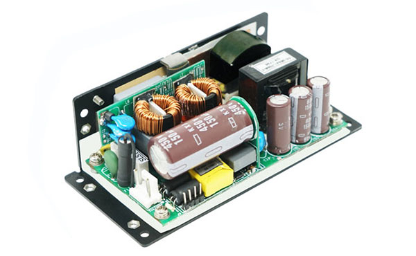
- There are burrs on the output side of the flyback transformer power supply I made, and the frequency of the burrs is the same as the switching frequency of the primary side. How can I eliminate the burrs?
Expert answer: A small inductor is connected in series between the secondary rectifier and the filter capacitor, but the inductor cannot be saturated when DC flows through it. The magnetic circuit of this inductor cannot be closed, and a large air gap must be left.
- How do you calculate the minimum DC voltage? I’ve looked at several versions but can’t find the most suitable one?
Smt pick and place Expert answer: I don’t quite understand what you mean by “minimum DC voltage” here? If it is the minimum input DC voltage of the switching power supply, it can generally be calculated based on the minimum input AC voltage. For example, if the minimum input AC voltage is AC100V (effective value), then the converted minimum DC input voltage is approximately 120V (average value). Because the maximum value after rectification and filtering is 140V, the minimum value is 100V, and the average value is 120V.
If the minimum DC voltage is the positive feedback voltage of a transistor self-excited switching power supply, then this voltage is best selected to be 2 times the operating voltage when the transistor is turned on, leaving 1 times as an adjustable margin. If the minimum DC voltage is the minimum operating voltage of the field effect transistor drive circuit, the minimum operating voltage cannot be less than 16V, because the driving voltage required for deep saturation of high-power field effect transistors is above 12V (preferably 20V).
- The efficiency of DC TO DC is a bit low recently. How to solve it?
Expert answer: Reduce the operating frequency, or replace the power switch tube with a high-speed switching tube. In addition, you can also increase the size of the transformer and reduce the value of the maximum magnetic flux density (Bm), that is, change the primary coil of the switching transformer. The number of turns increases because the hysteresis loss and eddy current loss of the switching transformer are proportional to the operating frequency and proportional to the square of the maximum flux density increment.
- Question: How to start with feedback loop design and compensation?
Smt pick and place Expert answer: The gain of the feedback loop is neither bigger nor better, nor smaller is better. When the gain of the feedback loop is too high, the output voltage will fluctuate around the average value. The higher the gain, the greater the amplitude of the fluctuation. In severe cases, oscillation will occur; when the gain of the feedback loop is too low, the output voltage will fluctuate. will be unstable. In order to stabilize the output voltage without oscillation, the feedback loop is generally divided into three loops. One loop is used to determine the size of the differential gain, the other loop is used to determine the size of the integral gain, and the third loop is Determine the size of the DC gain. By carefully adjusting the gains of these three feedback loops, the switching power supply can be stable without oscillation.
Best seller SMT Machine :Qihe smt line products
-
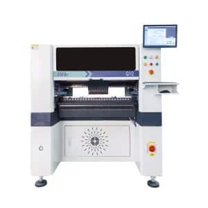
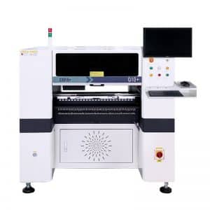
Q10 SMT Automatic pick and place machine 10 Heads 100 Slots High Precision and High Efficiency SMT/LED Assembly
-
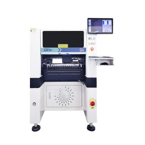
Q6 SMT pick and place machine 6heads 50slots With PCB Rail Servo Pick&Place Machine
-
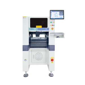
Q4 SMT pick and place machine 4heads 50slots With PCB Rail Servo Pick&Place Machine
-
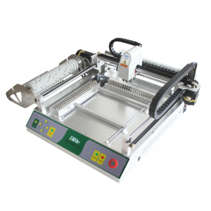
TVM802B Plus SMT pick and place machine 2heads 58slots desktop pick&place deluxe edition
-
QM10 SMT pick and place machine 10heads 80slots Fully Automatic Chip mounter SMT Assembly
-
TVM802BX SMT pick and place machine 2heads 46slots desktop pnp mounter deluxe edition
-
QL41 SMT pick and place machine 4heads 8slots LED for 1.2meters led strip pick&place machine
-
Q8 SMT pick and place machine 8heads 80slots Fully Automatic Chip mounter SMT Assembly
-
TVM802AX SMT pick and place machine 2heads 29slots desktop deluxe edition SMT Pick&Place Machine
What is SMT in engineering?
Surface mount technology is a part of the electronic assembly that deals with the mounting of electronic components to the surface of a PCB. Electronic components mounted this way are called surface-mounted devices (SMD). SMT was developed to minimize manufacturing costs while making efficient use of board space.Qihe SMT company develops and produces all kinds of SMT equipment suitable for world wide market, including pnp machine,reflow oven,stencil printer,pcb handling machines,and other Smt pick and place machine products.
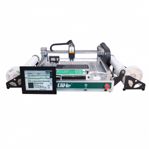
Small desktop pick and place machine TVM802A,TVM802B,TVM802AX,TVM802BX series suitable for beginners, for hobbiest or low vol usag.
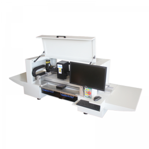
Advanced level 4-head LED strip placement QL41 led machines and with rail universal series Q4,TVM925S,TVM926S,pick and place
Fully automatic 6-10-head placement QM61,QM62,QM81,QM10,machines, which are suitable for high volume mass production in factories.
Know more about us https://www.qhsmt.com/about-qihe-smt-equipment/
Follow us on social media https://www.facebook.com/Qihesmt/
What is SMT in programming?
Offline Automated Programming vs Inline SMT Programming
Qihe pick and place machine can be programmed directly on the SMT equipment .
Or Coordinates can also be imported csv file through programming software.
Currently supported software such as protel,DXP,Altium Designer,Pads,Candes,proteus,DXP.
Inline SMT programming is a solution to consider for narrow segments of device programming requiring short programming times, with medium to high volume, for just one device type Smt pick and place machine .
WHAT IS SMT pick and place machine?
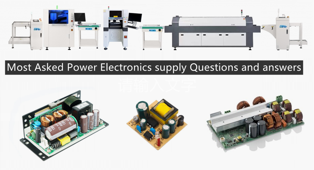
SMT (Surface Mounted Technology) is a comprehensive system engineering technology, which covers substrates, design, equipment, components, assembly processes, production accessories and management. When it comes to SMT pick and place machines, the automatic SMT production line requires automatic loading and unloading machine, automatic solder paste printing machine, placement machine, reflow soldering machine, AOI inspection equipment, conveyor,connecting table, etc. For these SMT assembly line equipment, Qihe SMT can offer you machines in prototype SMT line, small SMT production line, mass production SMT line at low SMT line cost. Contact us now if you are interested.pick and place
WHAT IS SMT ASSEMBLY LINE?
With the development of technology, future electronic products will be lighter, smaller and thinner. Traditional assembly technology can no longer meet the requirements of high-precision and high-density assembly. A new type of PCB assembly technology-SMT (Surface Mount Technology) has emerged. SMT Assembly is the use of automated machines to assemble electronic components on the surface of the circuit board. Its density, high speed, standardization and other characteristics occupies an absolute advantage in the field of circuit assembly technology. In addition, SMT assembly has a wide range of uses.
https://www.qhsmt.com/fully-automatic-smt-pick-and-place-machine-line/

