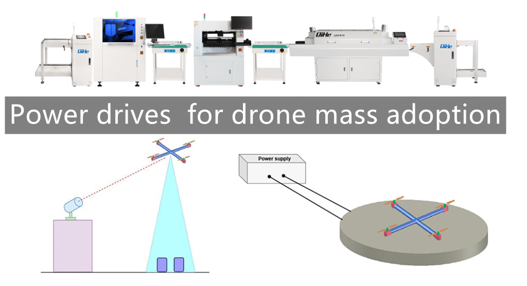
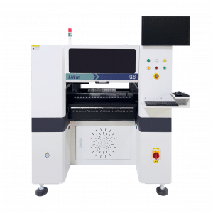
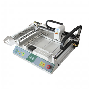
The emergence of drones has provided many conveniences for people’s lives, and has been widely used in all walks of life in society. However, its short battery life has always been a headache for researchers. At present, drones mainly rely on six kinds of power to complete complex tasks.Today qihe smt pick and place machine sharing power drives for drone mass adoption.
Lithium battery
Most drones are equipped with lithium batteries, but the effect can only last for about 20 minutes, and the batteries need to be disassembled and replaced frequently, which is time-consuming and laborious. In response to this phenomenon, the researchers explored two new sources of power, which greatly improved the efficiency of drones.
Hydrogen fuel cell
Hydrogen fuel cell replaces the lithium battery, which can support the continuous operation of the drone for two hours, and the charging is very fast;
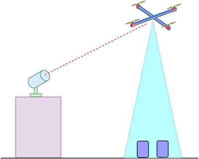
Laser transmitter
The laser transmitter supplies power to the drone. The laser beam emitted from the ground is converted into power by the receiver on the fuselage, which can almost support the drone to work all the time.
Solar power generation
UAVs that use solar power to generate electricity are usually equipped with lithium batteries and solar cells at the same time. When there is sunlight, solar energy can be used to provide flight power, and lithium batteries are used as backup batteries.
Power generation by internal combustion engine
Power generation by internal combustion engine can support the drone to fly at a speed of 100 kilometers per hour for 1 hour, but it is noisy and poses safety hazards, because there is flammable gas in the drone.
Wired cable power supply
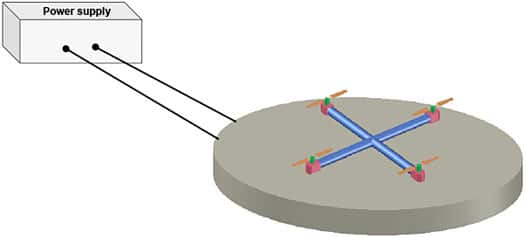
Using wired cable power supply can almost make the drone run permanently, and can also speed up the speed of data transmission from the drone to the computer. However, due to the limitation of wired connections, long-distance flight cannot be completed.
Hydrogen fuel cells and laser transmitters are two power sources that are favored by research and development groups due to their remarkable effects and high safety factor, and can also provide inspiration for the exploration of power sources for other aircraft in the future.
In addition, the UAV flight controller is the brain that connects all devices. There are more and more types of interfaces. Many novices are discouraged, and veterans are often at a loss. What are the common interfaces, and what are they used for on drones?
PWM
This is the first interface to be introduced, an interface that is inseparable from all aircraft models and drones. Single-wire signal, sending positive pulses periodically, changing the pulse width as a way to transmit information, one pin transmits one channel, often matched with ground wire and power line to control a steering gear or an ESC, it is the first one for getting started with drones or model aircraft Interfaces to know. The advantage is simple and stable transmission of a variable signal. The disadvantage is the low speed. The current common standard is 50 times or 300 to 400 times per second.
PPM
It is an upgraded version of PWM, that is, each signal cycle is changed to send a combination of multiple pulse widths to transmit change information of multiple channels at the same time. In the early days, it was also used for remote control radio signals and aircraft model simulator signals. Now it is mostly used for connecting receivers and flight controllers. There are many receivers with PPM signal output. Pants fart. Its advantage is that it transmits multiple channels stably, but its disadvantage is that it is slower.
S.BUS
It is a protocol designed by Japanese remote control manufacturer FUTABA to transmit multi-channel information with single-channel digital signals. There is only one signal pin and one reference ground wire, and it supports HUB expansion. Multiple servos and ESCs are connected to one signal source, so S. BUS is actually a bus, and its principle is actually a changing serial port protocol. For specific protocols, please refer to the article “PX4 Flight Control Development Notes-Chapter 5: PWM, PPM, S.BUS and DSM2” written by me on Baidu Library. Its advantage is pure digital signal, very reliable, with bus function. The disadvantage is that there are few compatible equipment belonging to the manufacturer’s technology. It is currently the best choice for flight control to connect to the receiver.
Relay
In fact, it is a digital IO signal, which only has two states of 0 and 1. Some pins of the flight controller are used to automatically control the camera shutter and the pesticide nozzle. The advantage is that it is reliable, and the disadvantage is that the amount of information is extremely small, wastes resources and has no functions such as verification.
Serial port
The serial port is the most common device interface in the control field at present, and the hardware forms include TTL, 232, 422, and 485. TTL is the basic signal, three-pin usage is common, one pin is used for signal input called RX, one pin is used for signal output called TX, and the other pin is the signal reference ground. Generally, 0 volts and 3-5 volts represent 0 and 1. The flight controller comes with this kind of serial port, and it will have many serial ports for connecting multiple devices. PIXHAWK flight controller has 5 ports. The voltage of the TTL signal is low, and it is not suitable for long-distance transmission of more than 1 meter in experience, so the 232 interface was developed, using positive and negative levels to indicate 0 and 1. Others are the same as TTL, which greatly extends the transmission distance, but the speed is still insufficient.
So the 422 interface was developed, and each pin of RX and TX becomes a pair of signal lines with positive and negative voltages jumping at the same time, so that the interference signal is ingeniously offset, and the transmission distance and speed double leap, but 5 lines are needed for debugging. It causes a lot of trouble, and only military products use this kind of serial port at present. The 485 serial port combines the advantages of 232 and 422. It uses a pair of positive and negative voltage signal lines to both send and receive, but it needs an additional signal to control the sending and receiving conversion. The 485 bus has bus characteristics and can be connected between two lines and the ground line. There are multiple devices, but you need to write programs to coordinate the work of sending and receiving, chip selection, arbitration, verification, etc. The workload is huge, and few people use it now.
SPI
This is a high-speed interface for on-board communication. It uses a master-slave design and a dedicated clock line. Each SPI has 4 pins master-in-slave-out, master-out-slave-in, clock and ground. The master device is responsible for information management, clock synchronization and communication of all devices. One SPI can connect multiple devices, but each must have a chip select. Because of the clock line, it is easy to achieve synchronous communication of all devices. Due to its stability and high-speed characteristics, it is used to connect all sensors and the main microcontroller on the flight control board.
I2C
In fact, it is I square C, which is a bus used to connect high-speed devices on the board. It has three signal lines, signal, clock and ground. It also adopts a master-slave design with a clock synchronization design, but the signal line needs to bear the input and output of multiple devices, and is managed by the master device. All devices on I2C have their own address, or label, and the master device uses this address to identify the device. In the flight control, it is used to connect many devices that are not very important, such as indicator lights, magnetic compass, airspeed, ultrasonic, laser ranging, etc. In order to save trouble, some manufacturers use this bus to connect multiple ESCs. This is very dangerous, because the 3-5v level is easily disturbed during long-distance transmission.
Can
The earliest bus interface designed for automobiles is said to be current transmission, so the anti-interference performance is super strong, and it is specially used for multiple long-distance transmissions between devices in a large interference environment. There are only two signal lines, H and L, on which all devices are connected, and the bus chip is responsible for arbitration. This is actually the best choice for equipment on UAVs, especially multi-rotor ESCs, but due to its complexity and the cost of interface chips, relatively few people use it. PIXHAWK flight controllers and ESC32 ESCs have already had this interface many years ago. So far no one cares.
AD
The analog-to-digital conversion interface, which is prone to interference, still exists, and its use is to measure voltage. At present, the flight controller is used to measure voltage and current. This method is relatively cheap and can also be used on small UAVs. Other distance detection equipment is still in use, but it is basically on the verge of being eliminated, and the effect is far inferior to digital equipment, but the cost is lower, such as airspeed and ultrasonic waves.
SDIO
Used to connect SD card or TF card for flight data recording. Due to the widespread application of TF cards, low cost, and satisfactory capacity and speed, it has gradually become an essential equipment for advanced flight control, used for flight records, accident analysis, fault diagnosis, etc.
USB
The civilian bus interface can connect multiple devices through the HUB, which can be said to be a perfect interface. However, the protocol is too complicated, the programming workload is huge, and the interface connection form is easy to cause problems, so special wires must be used, and the length cannot exceed 2 meters. On the flight control, it is mainly used for ground debugging, reading and writing parameters and other ground operations.
Read more: Power drives for drone mass adoptionBest seller SMT Machine :Qihe smt line products
-
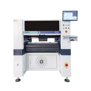
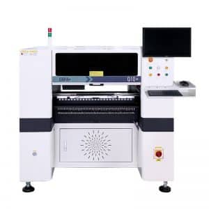
Q10 SMT Automatic pick and place machine 10 Heads 100 Slots High Precision and High Efficiency SMT/LED Assembly
-
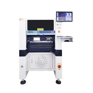
Q6 SMT pick and place machine 6heads 50slots With PCB Rail Servo Pick&Place Machine
-
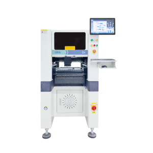
Q4 SMT pick and place machine 4heads 50slots With PCB Rail Servo Pick&Place Machine
-
TVM802B Plus SMT pick and place machine 2heads 58slots desktop pick&place deluxe edition
-
QM10 SMT pick and place machine 10heads 80slots Fully Automatic Chip mounter SMT Assembly
-
TVM802BX SMT pick and place machine 2heads 46slots desktop pnp mounter deluxe edition
-
QL41 SMT pick and place machine 4heads 8slots LED for 1.2meters led strip pick&place machine
-
Q8 SMT pick and place machine 8heads 80slots Fully Automatic Chip mounter SMT Assembly
-
TVM802AX SMT pick and place machine 2heads 29slots desktop deluxe edition SMT Pick&Place Machine
What is SMT in engineering?
Surface mount technology is a part of the electronic assembly that deals with the mounting of electronic components to the surface of a PCB. Electronic components mounted this way are called surface-mounted devices (SMD). SMT was developed to minimize manufacturing costs while making efficient use of board space.Qihe SMT company develops and produces all kinds of SMT equipment suitable for world wide market, including pnp machine,reflow oven,stencil printer,pcb handling machines,and other products.
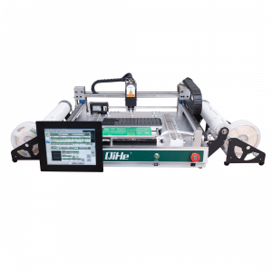
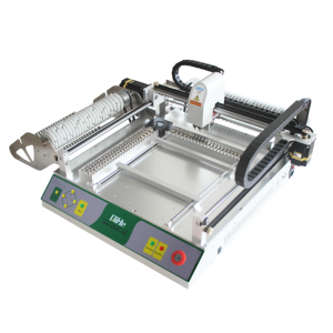
Small desktop pick and place machine TVM802A,TVM802B,TVM802AX,TVM802BX series suitable for beginners, for hobbiest or low vol usag.
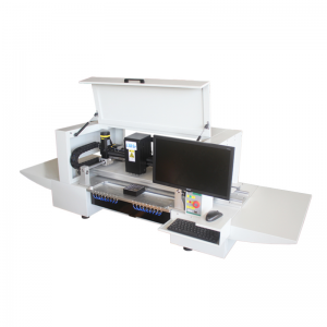
Advanced level 4-head LED strip placement QL41 led machines and with rail universal series TVM925S,TVM926S,
Fully automatic 6-10-head placement QM61,QM62,QM81,QM10,machines, which are suitable for high volume mass production in factories.
Know more about us https://www.qhsmt.com/about-qihe-smt-equipment/
Follow us on social media https://www.facebook.com/Qihesmt/
What is SMT in programming?
Offline Automated Programming vs Inline SMT Programming
Qihe pick and place machine can be programmed directly on the SMT equipment .
Or Coordinates can also be imported csv file through programming software.
Currently supported software such as protel,DXP,Altium Designer,Pads,Candes,proteus,DXP.
Inline SMT programming is a solution to consider for narrow segments of device programming requiring short programming times, with medium to high volume, for just one device type.
WHAT IS SMT pick and place machine?
SMT (Surface Mounted Technology) is a comprehensive system engineering technology, which covers substrates, design, equipment, components, assembly processes, production accessories and management. When it comes to SMT pick and place machines, the automatic SMT production line requires automatic loading and unloading machine, automatic solder paste printing machine, placement machine, reflow soldering machine, AOI inspection equipment, conveyor,connecting table, etc. For these SMT assembly line equipment, Qihe SMT can offer you machines in prototype SMT line, small SMT production line, mass production SMT line at low SMT line cost. Contact us now if you are interested.
WHAT IS SMT ASSEMBLY LINE?
With the development of technology, future electronic products will be lighter, smaller and thinner. Traditional assembly technology can no longer meet the requirements of high-precision and high-density assembly. A new type of PCB assembly technology-SMT (Surface Mount Technology) has emerged. SMT Assembly is the use of automated machines to assemble electronic components on the surface of the circuit board. Its density, high speed, standardization and other characteristics occupies an absolute advantage in the field of circuit assembly technology. In addition, SMT assembly has a wide range of uses.
https://www.qhsmt.com/fully-automatic-smt-pick-and-place-machine-line/

