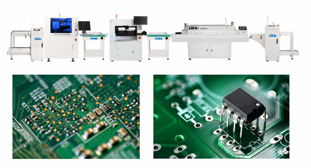
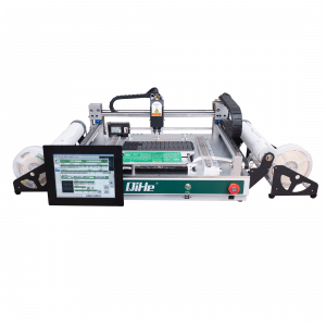
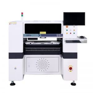
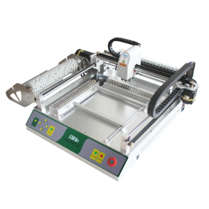
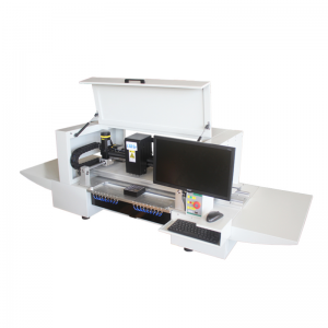
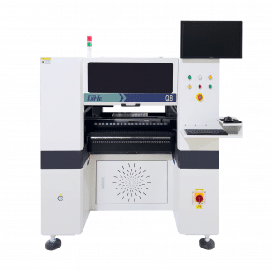
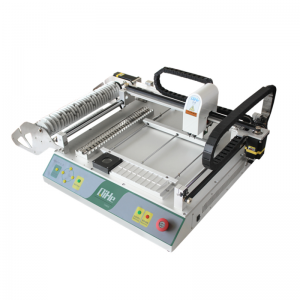
Hey guys today let’s Continue discuss about the several practical tips for PCB layoutlet’s when you doing pcb designing before you use QiHe smt equipments like smt pick and place machine , reflow oven, stencil printer

In the previous article we discussed five points ow let’s move on to the rest points
- The wires used at the input and output terminals should avoid being adjacent to and parallel to each other as much as possible.
It is best to add a ground wire between the lines to avoid feedback coupling.
- The corner of the printed wire is generally arc-shaped,
However, right angles or included angles will affect electrical functions in high-frequency circuits.
If it is necessary to take a right angle, two 135-degree angles are generally used instead of a right angle.
- Power cord design
According to the size of the printed circuit board current,
Try to increase the width of the power line and reduce the loop resistance.
At the same time, make the direction of the power line and ground line and the direction of data transmission the same,
This helps to enhance the ability to resist noise.
- Ground wire design
The principles of ground wire design are:
(1) The digital ground is separated from the analog ground.
If there are both logic circuits and linear circuits on the circuit board,
They should be separated as much as possible.
The ground of the low-frequency circuit should be selected as a single-point parallel connection ground as much as possible.
When the actual wiring is difficult, it can be partially connected in series and then connected to the ground in parallel.
High-frequency circuits should use multi-point series grounding, and the ground wire should be short and rented.
Use grid-shaped large-area foil as much as possible around high-frequency components.
(2) The ground wire should be as thick as possible.
If the grounding wire is made of a thin wire, the grounding potential changes with the change of the current,
degrades noise immunity.
Therefore, the ground wire should be thickened,
Make it pass three times the allowable current on the printed board.
If possible, the ground wire should be above 2~3mm.
(3) The ground wire forms a closed loop.
Printed boards consisting only of digital circuits,
Most of its grounding circuits are grouped into loops to improve the ability to resist noise.
- Decoupling capacitor configuration
One of the conventional practices in PCB design is to configure appropriate decoupling capacitors in various key parts of the printed board.
The general configuration principle of the decoupling capacitor is:
(1) Connect the electrolytic capacitor of 10 ~ 100uf across the input terminal of the power supply. If possible, it is better to connect more than 100uF.
(2) In principle, each integrated circuit chip should be equipped with a 0.01pF ceramic capacitor,
If there is not enough space in the printed board,
A 1-10pF capacitor can be placed every 4-8 chips.
(3) Weak anti-noise ability,
Equipment with large power changes when turned off
, such as RAM, ROM storage devices,
The decoupling capacitor should be connected directly between the power line and the ground line of the chip.
(4) The capacitor lead should not be too long,
In particular, high frequency bypass capacitors cannot have leads.
- In addition, the following two points should be noted:
(1) When there are touch devices, relays, buttons and other components in the printed board.
When operating them, a large spark discharge will be generated,
The RC circuit shown in the attached figure must be used to absorb the discharge current.
Generally, R takes 1 ~ 2K, and C takes 2.2 ~ 47UF.
(2) The input impedance of CMOS is very high and is susceptible to induction.
Therefore, when in use, the unnecessary terminals must be grounded or connected to the positive power supply.
QHSMT is an enterprise specializing in the production of SMT equipment, smt production line layout,like pick and place machine ,reflow oven,stencil printer ,smt pick and place machine,pnp,pick&place,pcb assembly,smd chip shooter,pnp machine,chip mounter,smt line,welcome to send inquiry
you can choose a reflow oven to meets your need like qfr630,qrf835,qrf1235
stencil printer model qh3040,qp3250,qfa5060
Also we have different kinds of smt pick and place machine like tvm802a,tvm802b,tvm802ax,tvm802bx,tvm925s,tvm926s,ql41,qm61,qm62,qm81,qm10
-
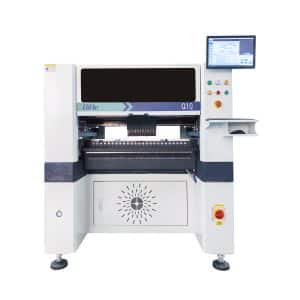
Q10 SMT Automatic pick and place machine 10 Heads 100 Slots High Precision and High Efficiency SMT/LED Assembly
-
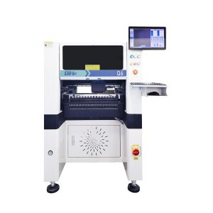
Q6 SMT pick and place machine 6heads 50slots With PCB Rail Servo Pick&Place Machine
-
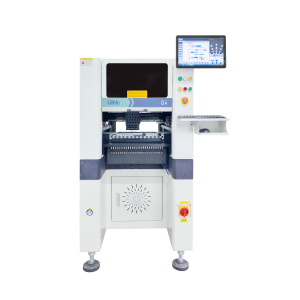
Q4 SMT pick and place machine 4heads 50slots With PCB Rail Servo Pick&Place Machine
-
TVM802B Plus SMT pick and place machine 2heads 58slots desktop pick&place deluxe edition
-
QM10 SMT pick and place machine 10heads 80slots Fully Automatic Chip mounter SMT Assembly
-
TVM802BX SMT pick and place machine 2heads 46slots desktop pnp mounter deluxe edition
-
QL41 SMT pick and place machine 4heads 8slots LED for 1.2meters led strip pick&place machine
-
Q8 SMT pick and place machine 8heads 80slots Fully Automatic Chip mounter SMT Assembly
-
TVM802AX SMT pick and place machine 2heads 29slots desktop deluxe edition SMT Pick&Place Machine
WHAT IS SMT pick and place machine?
SMT (Surface Mounted Technology) is a comprehensive system engineering technology, which covers substrates, design, equipment, components, assembly processes, production accessories and management. When it comes to SMT pick and place machines, the automatic SMT production line requires automatic loading and unloading machine, automatic solder paste printing machine, placement machine, reflow soldering machine, AOI inspection equipment, connecting table, etc. For these SMT assembly line equipment, Qihe SMT can offer you machines in prototype SMT line, small SMT production line, mass production SMT line at low SMT line cost. Contact us now if you are interested.
WHAT IS SMT ASSEMBLY LINE?
With the development of technology, future electronic products will be lighter, smaller and thinner. Traditional assembly technology can no longer meet the requirements of high-precision and high-density assembly. A new type of PCB assembly technology-SMT (Surface Mount Technology) has emerged. SMT Assembly is the use of automated machines to assemble electronic components on the surface of the circuit board. Its density, high speed, standardization and other characteristics occupies an absolute advantage in the field of circuit assembly technology. In addition, SMT assembly has a wide range of uses.
WHAT IS SMT PROCESS?
There are mainly three steps in SMT assembly line process flow: solder paste printing, components placement and reflow soldering.
- Solder Paste Printing
Its function in SMT line process is to print the solder-free paste on the pads of the PCB to prepare for the soldering of the components. The equipment used is a screen printing machine, located at the forefront of the SMT production line. - Components Placement
Its function is to accurately install the surface mount components on the fixed position of the PCB. The equipment used is a placement machine, located behind the screen printing machine in the SMT production line. - Reflow Soldering
Its function in SMT manufacturing line is to melt the solder paste so that the surface mount components and the PCB board are firmly bonded together. The equipment used is a reflow oven, located behind the placement machine in the fully automatic SMT production line.
