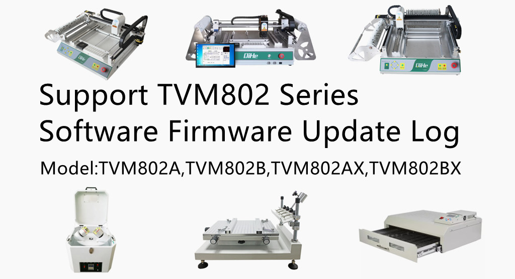
TVM802A TVM802B Series desktop smt pick and place machine Software Firmware Update log
Original factory model: TVM802A,TVM802B,TVM802AX,TVM802BX,
Distributor possible model:SMT TVM802C,TVM802D,TVM802AS,TVM802BS,
Previous version V3.01 – V3.37
Current Updatable Version V3.38
Note1:
Email to your customer service manager to update the latest software.
Please provide your device model, Sn-number and current software version code .
Note2:
If you cannot find or forget your manager’s contact or even purchased from a distributor.
Please leave us a message in our website dialog box or email us.
In addition to the device model,SN number and current software version code.
we also need your explain which way you purchased from and your email which we’ll send the software to .
After verifying your information, we will update the software to you ASAP.
Note3:
The earliest V1.XX or V2.XX series cannot use the V3.XX version software .
The V2.XX series latest updatable version is V2.39 .
Note4:
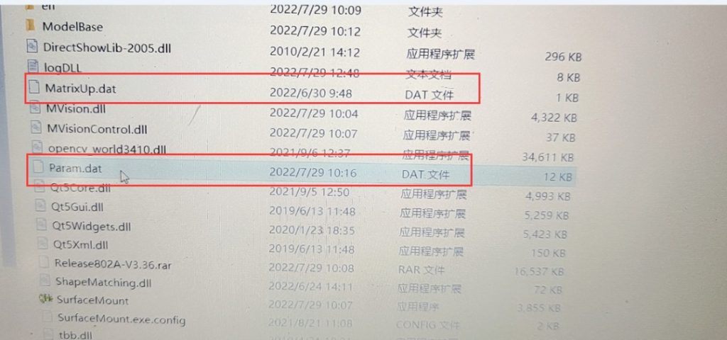
you need replace two files from the old vision to the new vision
param.dat
matrixup.dat
copy those two files into the new vision
V3.38—– 2022/10/31
1.Fix the position of the search button.
2.Correct some translation errors on the English interface.
3.Compatible with csv file formats: \”\t,\”
V3.36—– 2022/7/4
- Modify the bug that the changes in PCB Array coordinates shall be incorporated into the calculation of mark points.
- 2.Compatible with csv file formats: origin x(mm)/ origin y(mm)/rotate
V3.35—– 2022/5/26
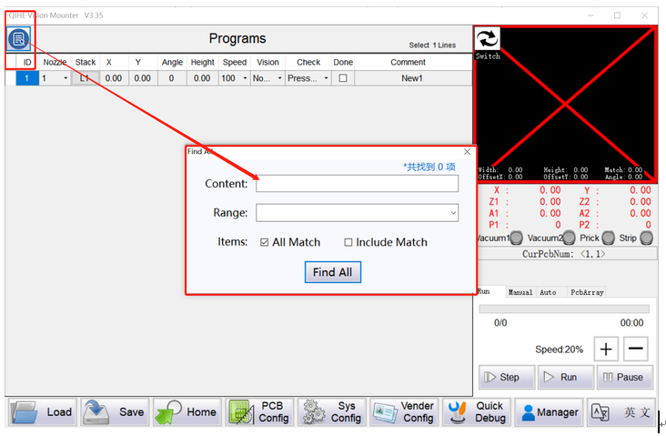
1. The component table adds the search function;
2.Modify the bug that the software crashes when the coordinates of the stack s are displayed as empty in the Quick Debug.
V3.33—– 2022/4/15
1.Modify the bug that save fails when setting the camera orientation in the Quick Debug.
V3.32—– 2022/1/31
1. Modify the BUG when the stack is set None, the file loading error occurs.
V3.31—– 2021/10/9
1.Added the software language switching function.
2. Added the software account management function.
V3.30—– 2021/7/21
1. Modify the BUG when passing vision the order of nozzles is wrong.
V3.29—– 2021/3/26
1、Modify the BUG about the calculation order of the PcbArray’s coordinate.
V3.28—– 2021/3/25
1、Optimize the “Auto Go Home” function, cancel this function switch, and increase the parameter “Auto Go Home Interval”.
2、
V3.27—– 2020/12/1
1、Compatible with TXT coordinate file exported by Sprint Layout 6.0 software.
2、Modified the BUG when set position of IC Array.
V3.26—– 2020/10/12
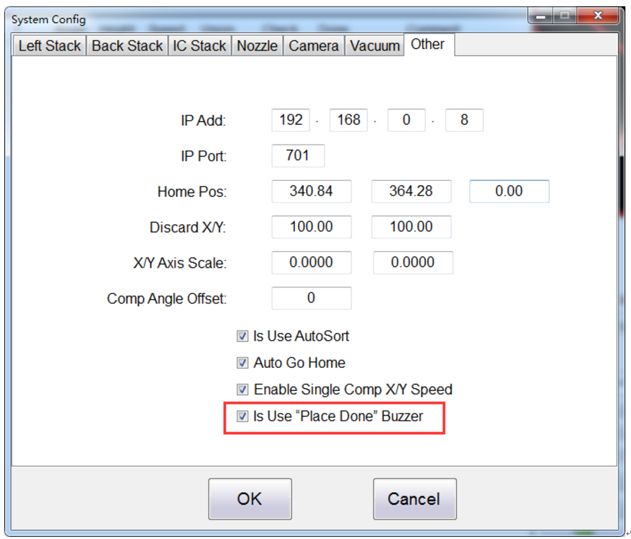
1、Added a switch for “alarm buzzer sound for place done”。
V3.25—– 2020/8/17
1、Modify the limit of Z-Axis down height;
2、The alarm buzzer when the head is completed is turned off at the next start;
3、The alarm buzzer when the head is completed is automatically turned off after a period of time;
4、Compatibility of related parameters in different versions when reading system data files。
V3.24 —– 2020/7/18
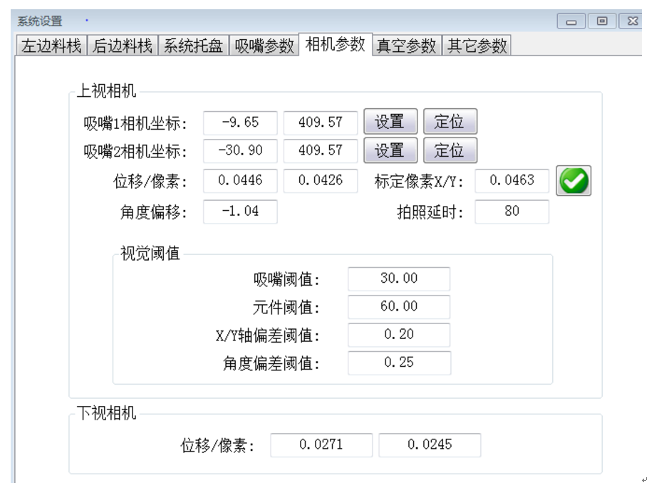
1、Optimize camera coordinate parameters。
V3.23 —– 2020/4/22
1、Modify the BUG about “an error occurred when setting the coordinate parameter to IC stack”;
2、Modify the BUG about “ the descending height of Z1 and Z2 Axis are inconsistent”;
3、Add the maximum allowable range of position offset value during vision measurement;
4、Optimize the speed of the reel.
V3.22 —— 2019/11/26
1、Modify the function that the coordinate of IC Stack in the SysConfig can be set and moved with down vision.
V3.20 —— 2019/8/26
1、Optimize the data transfer protocol.
V3.19 —— 2019/5/23
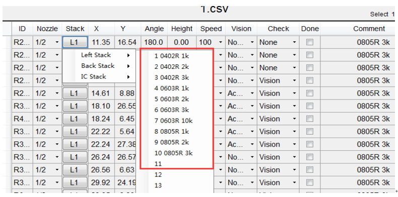
1、Add the interface display. When selecting the stack in the component list, the corresponding component name is displayed after the serial number of the stack. This name corresponds to the edited component name in “System Config – Stack – Comp”.
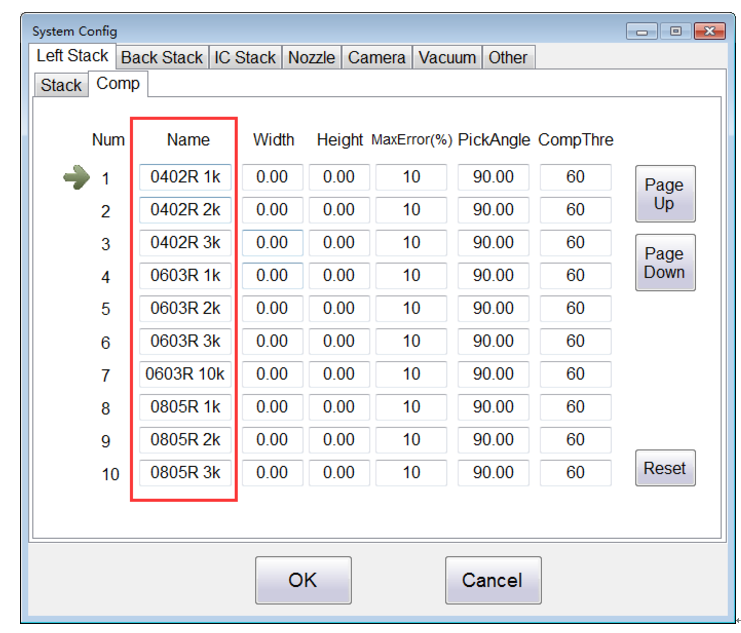
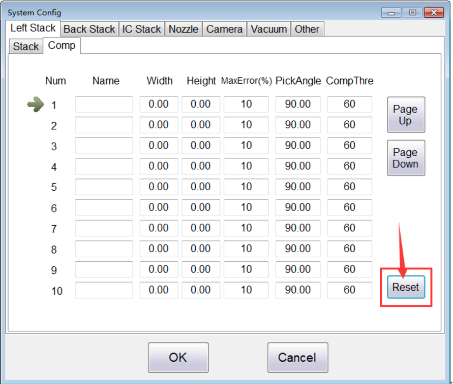
2、Add a new button. In the “System Config – Stack – Comp” ,add the “one-key reset” function, the data of the component will be restored to the system default settings;
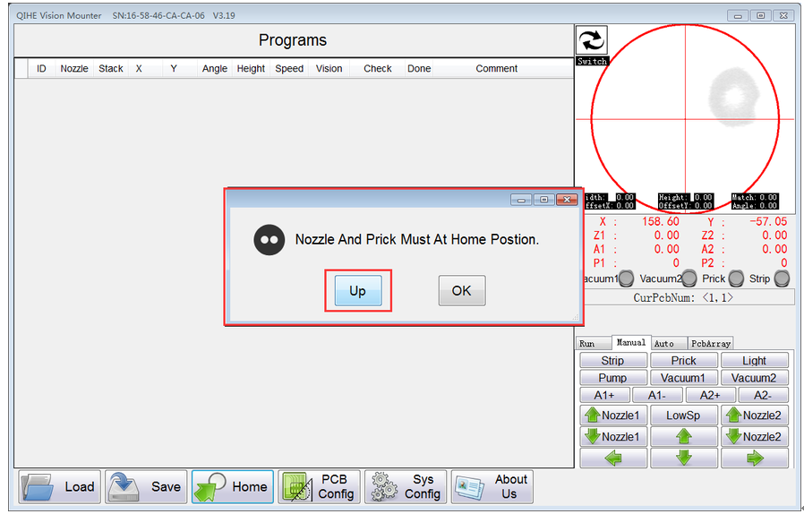
3、Optimize the interface display. Optimize the alarm display when the Z axis and the needle are not properly raised, and add a button to eliminate the alarm and lift the needle and Z axis;
4、Modify the BUG about“the software will automatically generate ‘Param.data’ file in the directory where the software is located when the software is opened in the broken line state”;
5、Optimize the placement sequence of the components after using the the function ‘Missing Check’.
V3.18 —— 2019/3/20
1、Modify the BUG about “When the English version software loads the CSV file,the parameter‘Check’ can’t be loaded correctly ”;
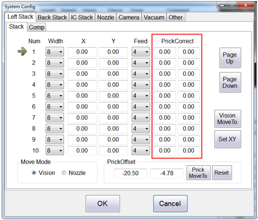
2、Modify the range of parameter “PrickCorrect”to (-4 ~ 4mm).
V3.17 —— 2019/3/5
1、Modify the BUG about “software error occurred while saving CSV file”.
V3.16 —— 2019/1/5
1、Modify the BUG about “when both nozzle select the type ‘Vision’ of ‘Missing Check’ and select the type ‘Accurate’ of ‘Vision’ at the same time,the No.2 nozzle will throw component abnormally ”.
V3.15 —— 2018/12/25
2、Modify the BUG about “the mounting head works incorrectly when discarding the components and re-feeding at the IC Stack”;
3、Modify the BUG about “the ‘Check’ column of the components list can not be displayed after loading the CSV file”.
V3.14 —— 2018/11/21
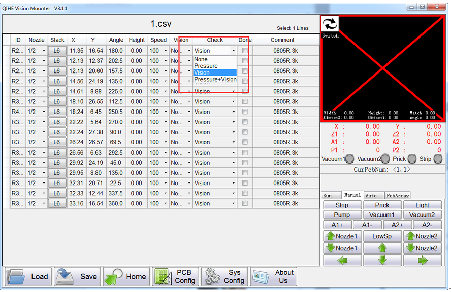
1、Add a new function about Missing Check:use vision to check the size of component;
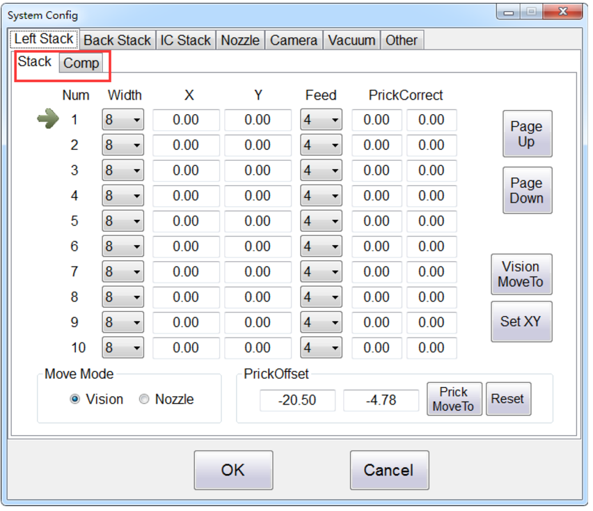
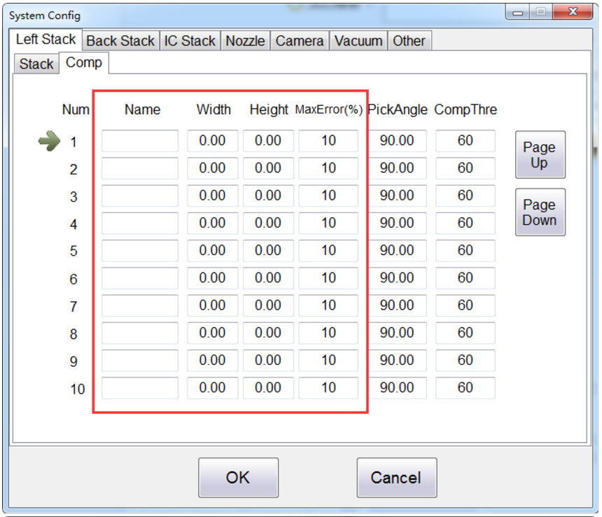
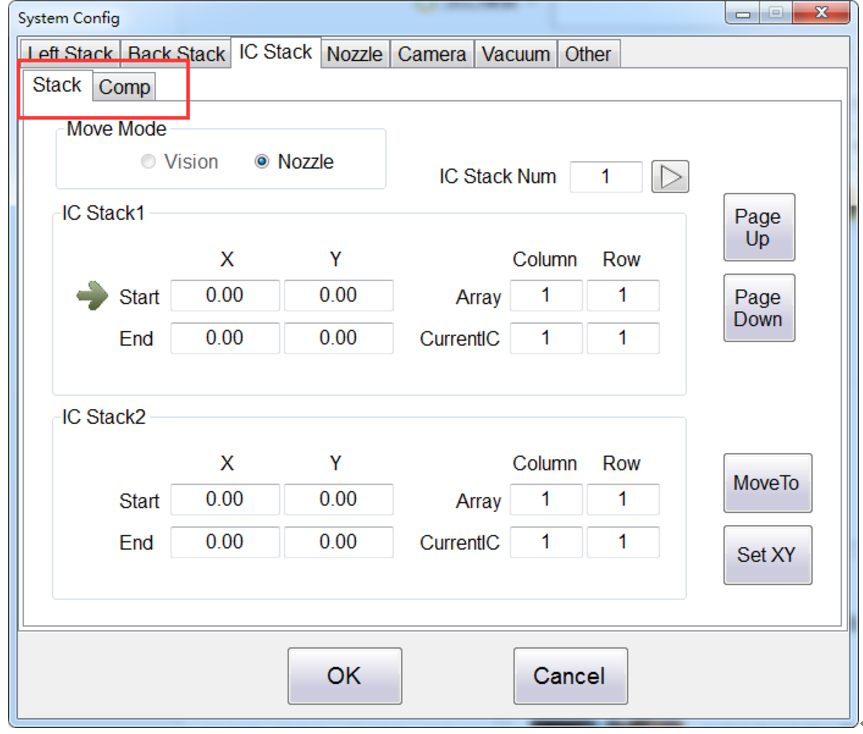
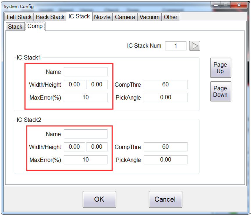
2、Modify the interface of Stack in the “Sys Config”;Add the new parameters about components:“Name”、“Size(Width/Height)”、“Max Error(Default is 10%)” .
Note: The data of Stack will be saved to the file which is named as “Param.dat” in the “.EXE” file directory,and the data in the Comp interface will also be saved to the CSV file.
V3.13 —— 2018/10/23
1、Modify the BUG about “When change the CSV file which contains the PCB Array settings, it cause a software error;”
2、Modify the BUG about “the function of shaking the prick needle is disabled.”
V3.12 —— 2018/10/11
1、The down height range of Z Axis is adjusted to “-12.5 ~ 0”;
2、Modify the BUG about “After the components pass through the vision,then the components is discarded and picked again.When the vision recognition is performed again,the correction effect of vision is superimposed.”;
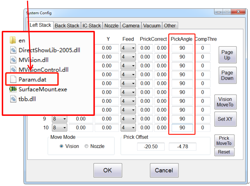
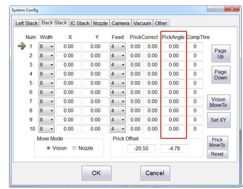
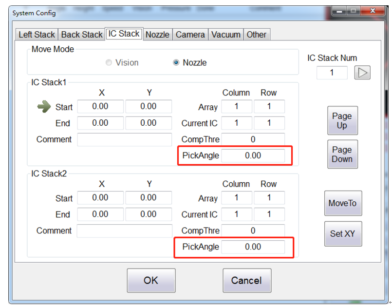
3、 Add the parameter “Pick Angle” into “System Config – Left Stack / Back Stack / IC Stack”,each Stack has its own Pick Angle.
Left Stack: The default value is “90”,save the data to the “Param.dat” in the “.EXE” file directory;
Back Stack: The default value is “0”,save the data to the “Param.dat” in the “.EXE” file directory;
IC Stack: The default value is “0”,save the data to the “CSV” file.
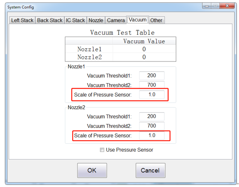
4、 Add the parameter “Scale of Pressure Sensor” into “System Config – Vacuum”;
5、 Add the parameter “Enable Single Comp X/Y Speed” into “System Config – Other”;
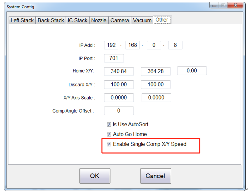
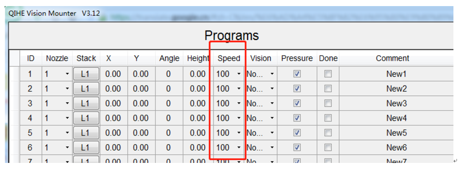
This parameter is checked. The “speed” in the component parameter table will be applied globally (including the X/Y/Z axis, etc.), otherwise it will only affect the speed of the Z axis;
6、Modify the BUG about“When adjust the Prick Offset,the detection is not added after the error occurs”;
7、Modify the BUG about “The parameter ‘Template Size’ in the PCB Config does not match the actual value”;
8、Modify the BUG about “When click the button ‘Reset’ in the PCB Config,some parameters can not be reset correctly”;
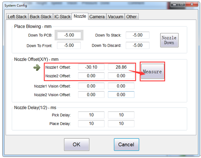
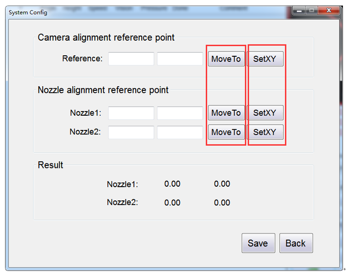
9、Optimize the adjustment scheme of Nozzle Offset which is between nozzle and the center of the down vision,add a new interface that is more intuitive;
Instructions:
(1) Select any reference point, move the down camera to amid the reference point and set the current coordinates;
(2) Moving the nozzle 1 and the nozzle 2 respectively to amid the reference point and set the current coordinates;
(3) The value displayed by the detection result is the offset value of the nozzle to the center of the down camera.
10、Optimize the interactivity about the function of PCB Array.
V3.11 —— 2018/7/20
1、Modify the BUG about “Place Selected Components”;
2、Optimize the Speed,reduce the speed with every component which in the Components Table is only effective when the Z axis drops the components;
3、Compatible with the coordinate file of TXT format;
4、When the coordinate file is imported, the space characters before/after the content of the “Comment” item in the list are automatically deleted;
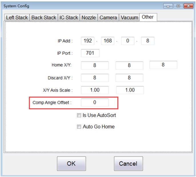
5、Add the parameter “Comp Angle Offset” into “System Config – Other”;
V3.10 —— 2018/6/20
1、Modify the BUG about “Aimed With Camera”;
2、Add the function that the Z Axis could return to the origin home,and check all the time if the Z Axis is at the origin home.
V3.09 —— 2018/04/24
1、Modify the BUG about “Image Template”:the vision can’t switch when the down vision identification is in mistake, and the vision can’t identify before get the pictures of Image Template.
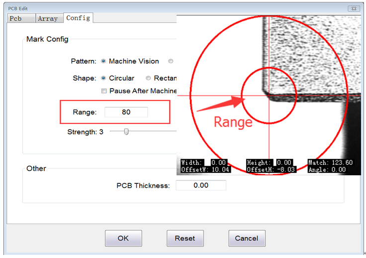
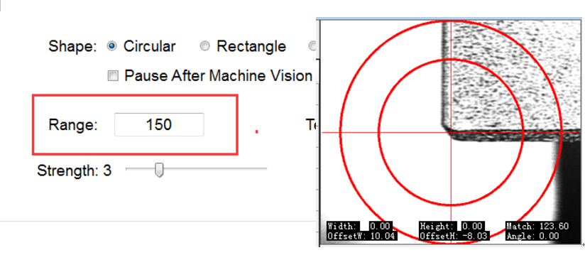
2、Add the parameter “Range” into “Image Template”;
3、Modify the BUG when use the function “PCB Edit – Array – Auto”,can’t restart.
V3.08 —— 2018/04/04
1、Modify the BUG that the data “Angle” which is in the list “Sub Pcb Reference Point Pos” didn’t have any effect;

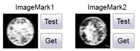
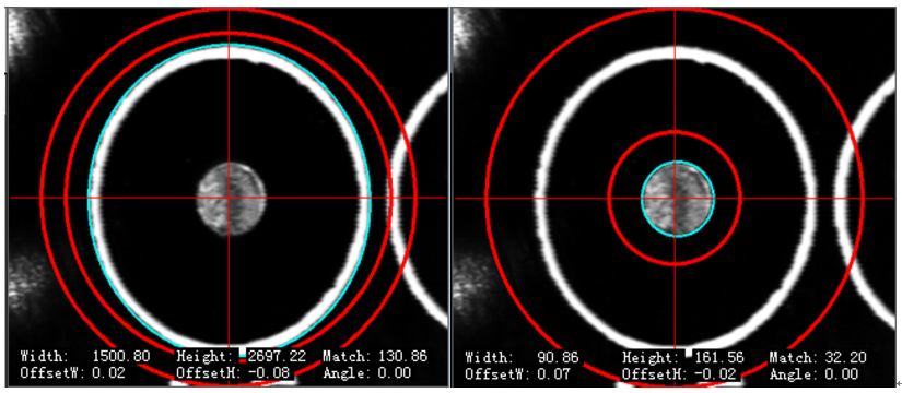
2、Add one new algorithm for the recognition function of mark point :“Image Template”.And optimize the interface.
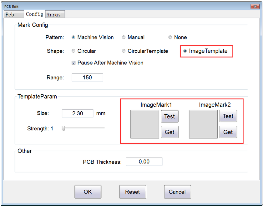
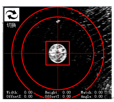
b、Click the button “Get” to get the image template of Mark.
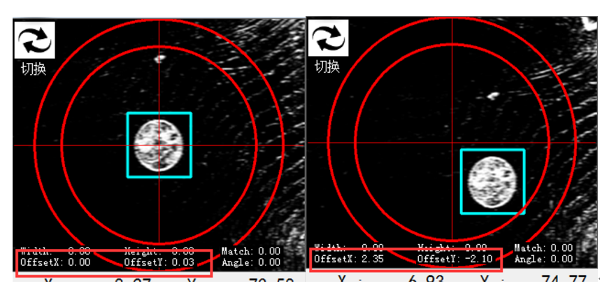
c、Click the button “Test”。The Bule Box is the image which matches the image template. Below the vision screen,“OffsetX” and“OffsetY”reflect the offset of the matched template.
d、The data of “ImageMark” are saved to the CSV file.
V3.07 —— 2018/03/20
1、Optimize the Speed of Z Axis;
2、Modify the BUG when use “MakeRule”,the coordinate will be messy code.
V3.06 —— 2017/11/28
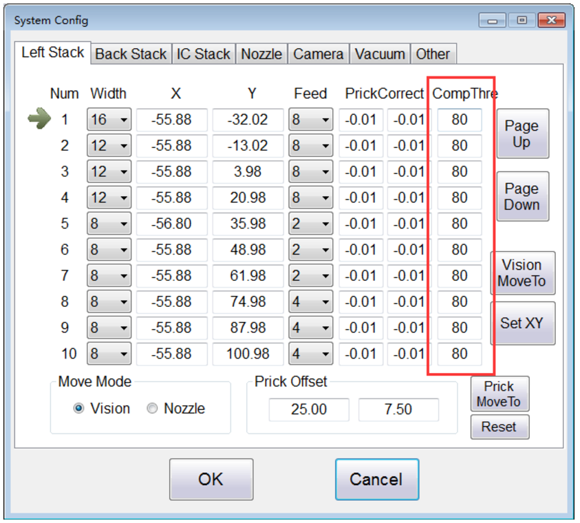
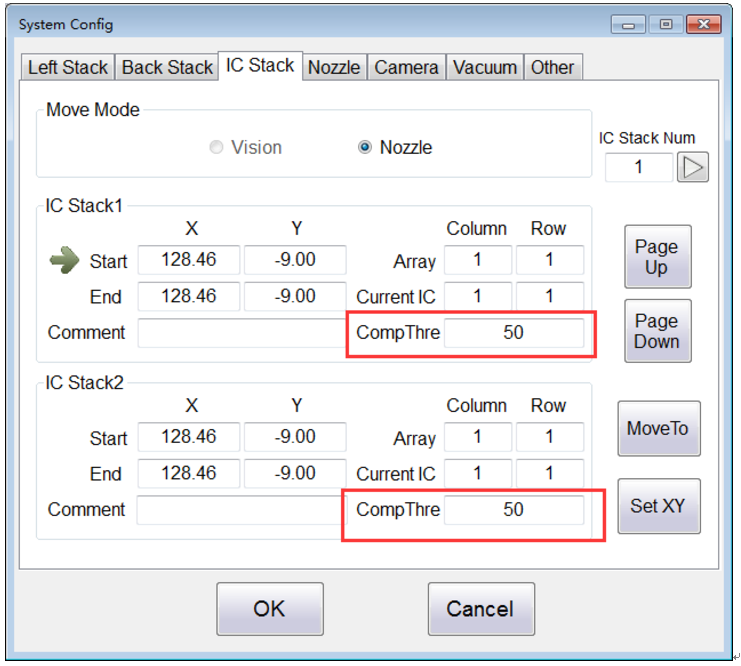
1、Optimize the parameter “Component Threshold” which is used in the Vision of the Components, each of The Stack(Left/Back/IC) has its own Component Threshold.The parameter data of the Left/Back Stack is saved to the main board, and the parameter data of the IC Stack is saved to the CSV file.
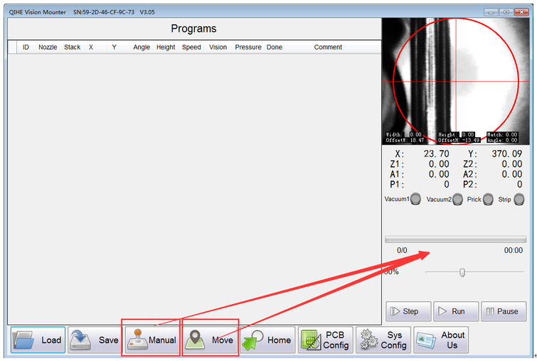
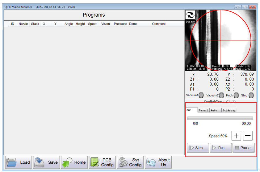
2、Optimize the interface:
(1)Move the interface of “Run”“Manual”“Auto”;
The old:
The new:
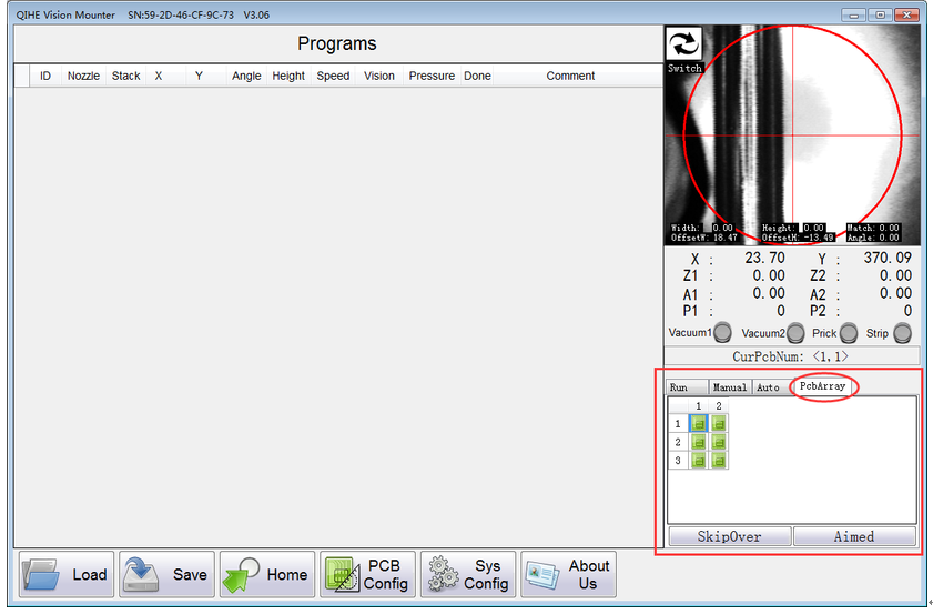
(2)Add a quick menu of “PcbArray”;
(3) Add the button which could switch the Vision;
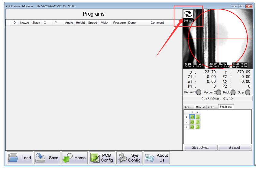
(4)Modify the method of change the speed,now use the button to add and subtract the speed.
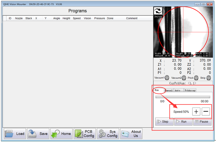
3、Optimize the function of “PcbArray”, and the components in the list of each board are independent and can be changed manually.
4、Modify the BUG that the Tip Box of “As The Camera Error !”appears abnormally.
V3.05 ——— 2017/9/28
1、Modify the BUG that can’t use the function “Amied With Camera”of right-click menu.
2、Optimize the Visual display.
V3.04 —— 2017/9/25
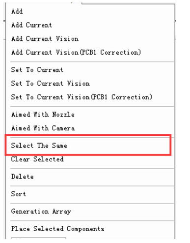
1、Modify the function “Select The Same” of right-click menu, the words of the selected lines are not case sensitive.

2、Optimize the leak detection and increase the alarm about no components are picked and put.
3、Add the function that the direction key on the keyboard can operate the machine, and the space key can switch the movement speed (LowSp/HightSp).
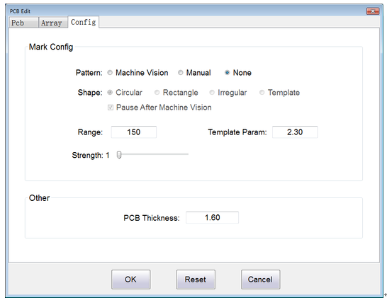
4、Optimize the pages of “PCB Config”
(1)Interface Optimization
Three functional zones are divided according to different functions:
“PCB”:Set the mark points of each circuit board.
“Array”:Make the PCB Array rules.
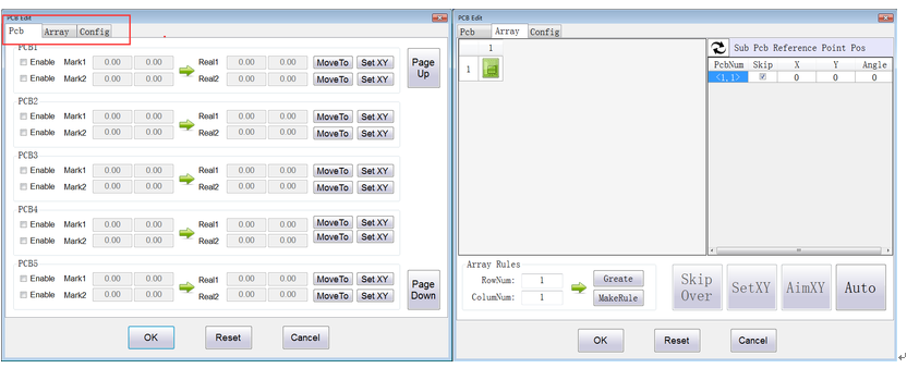
“Config”:Identification parameters about mark points,and circuit board’s thickness.
(2)The Function Of PCB Array Optimization
When the number of circuit boards exceeds 5,this update method is recommended.
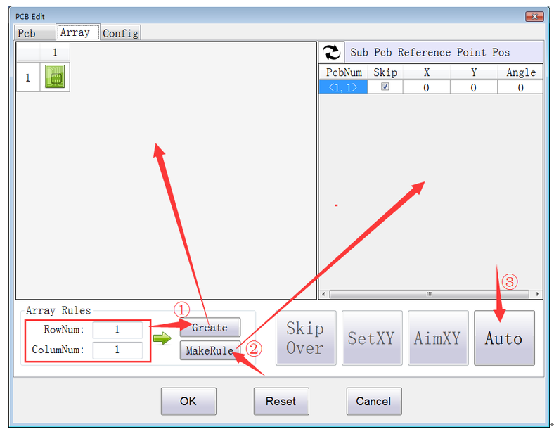
Figure 1
①According to the actual situation, fill in the number of rows and columns,then click “Create” to create pcb array(displaying in the left list(Figure 1)).
②Measuring the space of each Sub PCB.Respectively capture the reference point coordinates of these three Sub PCB such as the 1,2,3 board(displaying in the Figure 2 ).Then click “Next” to calculate the reference point coordinates of each Sub PCB.And the information of the reference point coordinate is displaying in the right list(Figure 1).
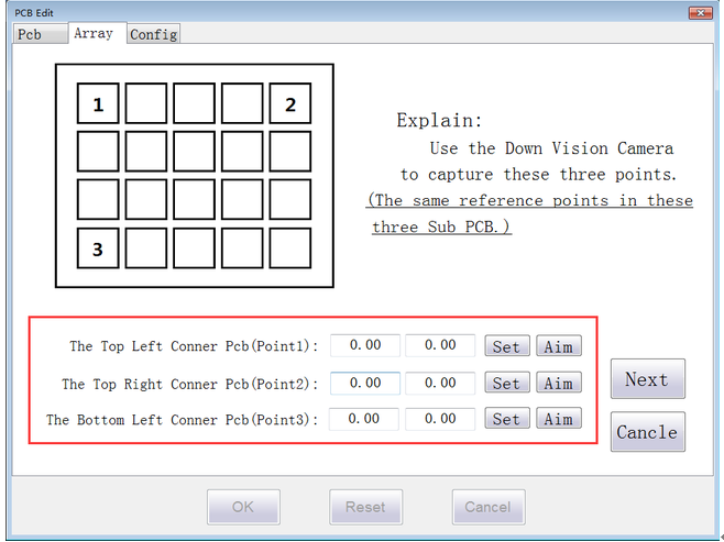
Figure 2
③Click “Auto” ,automatically identify each reference point and correct the coordinates.
(3)Introduction of relevant interactive functions
①The parameters of the PCB Configuration is saved to the CSV File.Please save it in time.
②Click and select the graphic elements in the left list,the corresponding information of the Sub PCB which is selected will be displaying in the right list.The information include the reference point coordinate of each Sub PCB and the coordinate of every component which is on this Sub PCB.
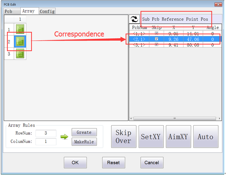
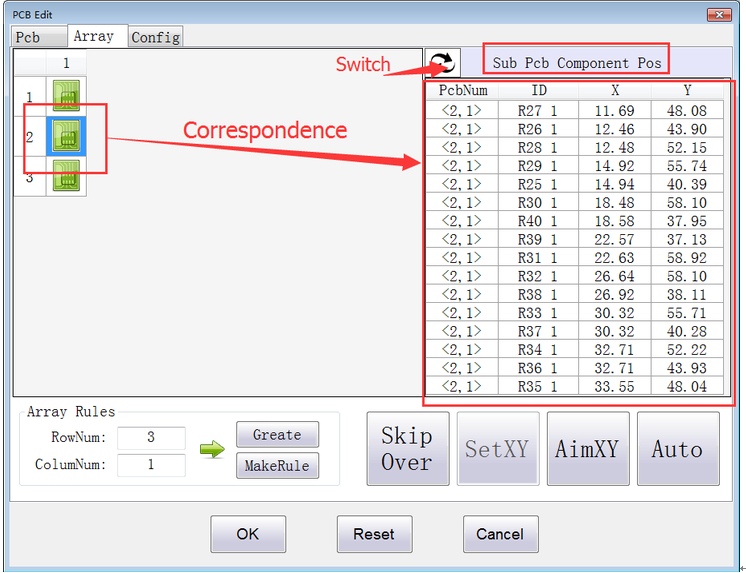
③Click the button in the top left of the right list.It will switch the different data.
④About the function of button.
“Skip Over”:Click and select the corresponding Sub PCB in the left list,then click this button to decide whether pick and put this Sub PCB.
“Set XY”:Move the Down Vision Camera to aim at the point ,and then capture the coordinate.
“Aim XY”:According to the selected point coordinate,move and aim at the point.
“Auto”:Automatic recognition the reference points of each Sub PCB.
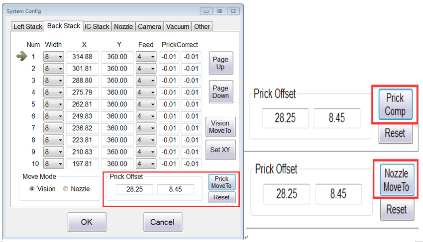
6、Optimize the step of “Prick MoveTo”( Prick MoveTo、Prick Comp、Nozzle MoveTo),“Reset”is to make the prick needle and nozzle to zero.
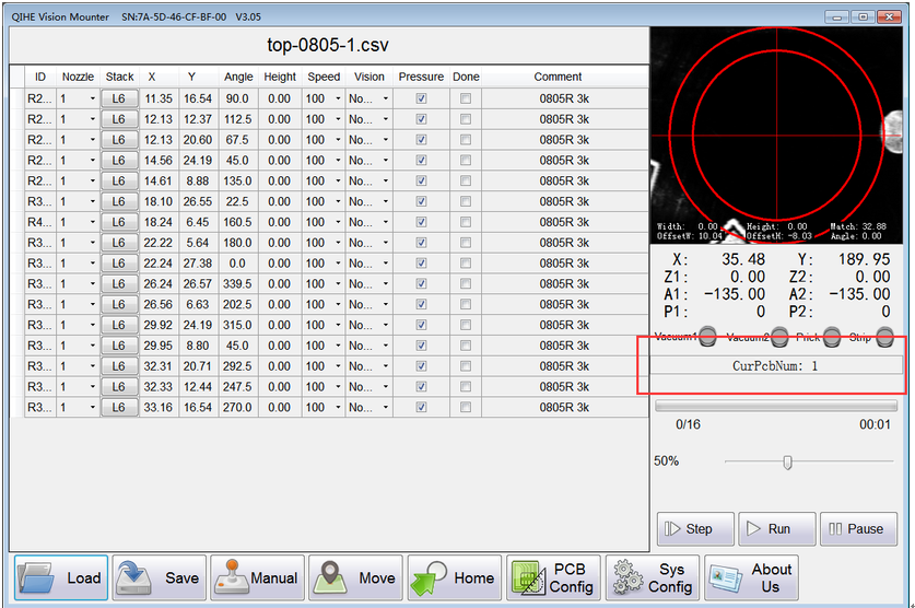
7、Add a button to display “CurPcbNum”,and can one step jump back to the beginning of the first PCB.
V3.03 —— 2017/6/29
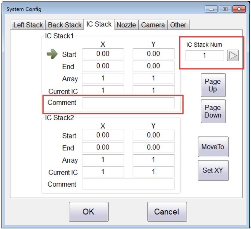
1、The data of IC Stack can be saved to the csv file.
2、Add the parameter : “Comment”.
It is used to record the information about your IC.
3、Add the function that you can click the button to find the information of the IC Stack according to the number.
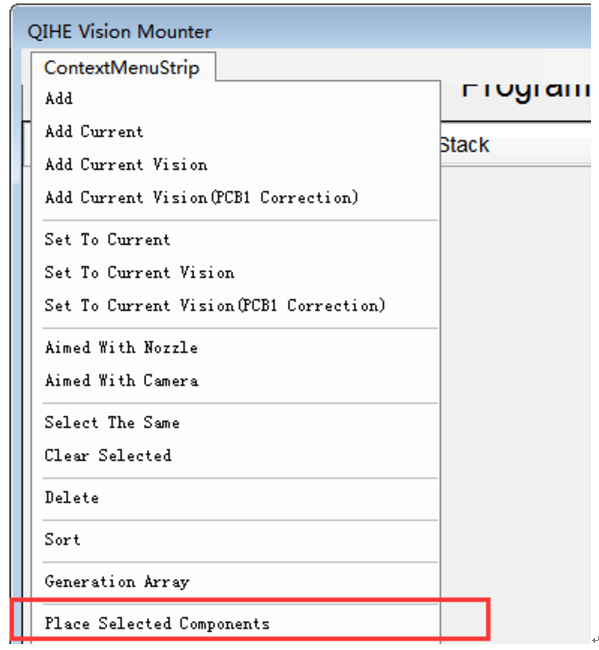
4、Add the function “ Place Selected Components ” into right-click menu.
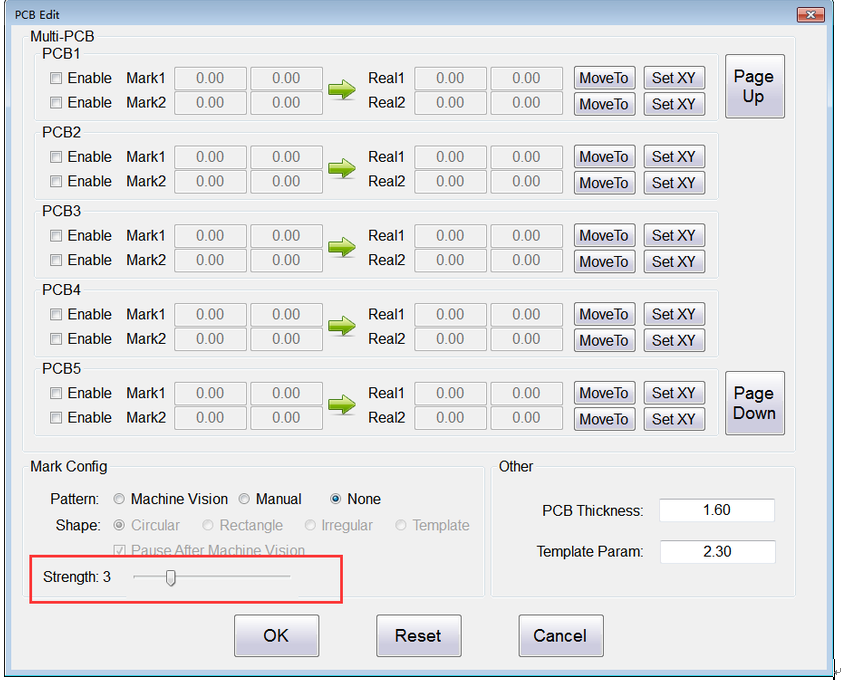
5、Add the function “ Strength ” into “ PCB Config — Mark Config”. This function can enhance the recognition strength of Mark Point according to the light source of different environment.
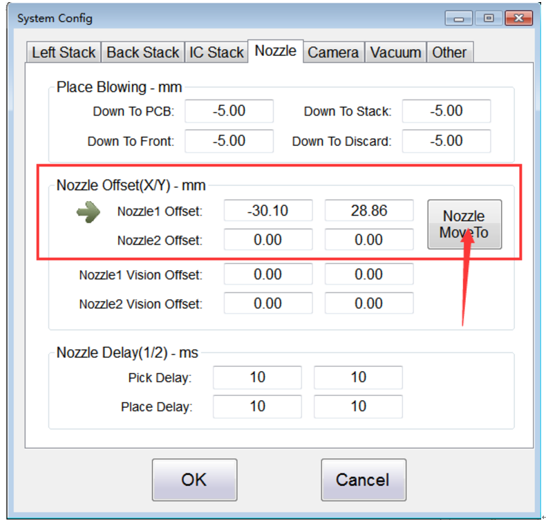
6、Optimize the adjustment of the parameter “ Nozzle Offset ”. To make it easier to adjust the offset between the nozzle and the down vision camera.
Usage:
(1)、Let the down vision camera aim at a reference point( it can be any component coordinates);
(2)、Click the button “ Nozzle MoveTo ”;
(3)、Click the “ Nozzle Down ”;
(4)、Move the pick and place head, let the nozzle aim at the selected reference point;
(5)、Click the “ Nozzle Up ”;
(6)、Click the “ Camera MoveTo ”
(7)、The above steps are a cycle.You should replay these steps until get the correct “ Nozzle Offset ”.
V3.02 —— 2017/6/5
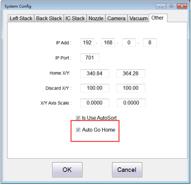
1、Add the Parameter : “Auto Go Home”.
It’s a switch whether to use this function.
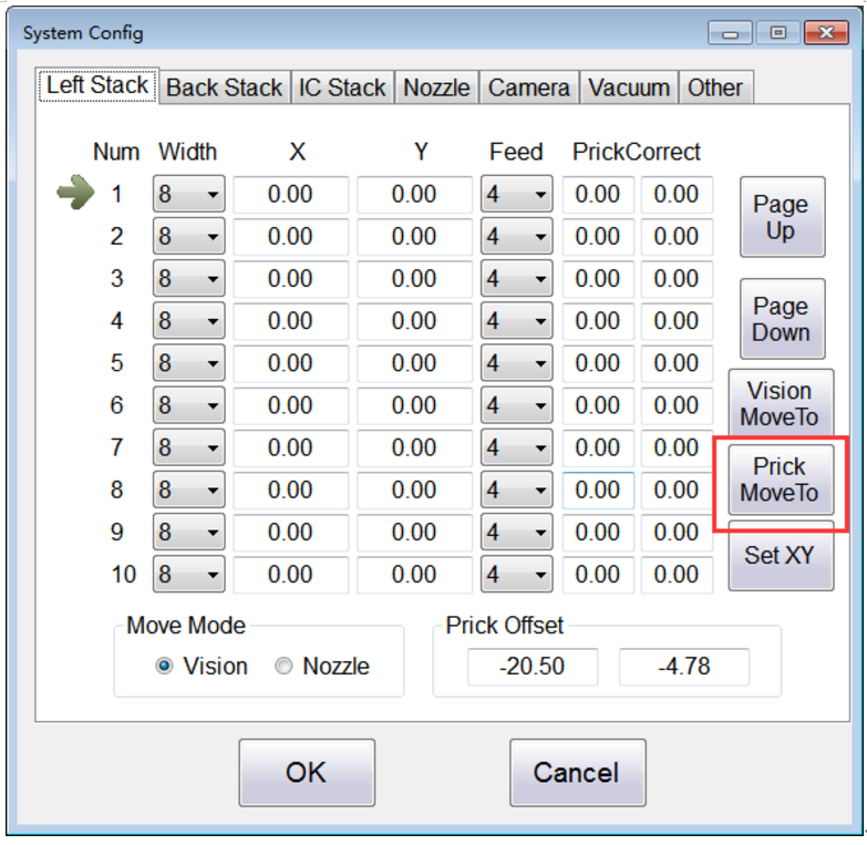
2、Add the function that directly position the prick needle through a button.
3、Add the function that there are two ways to get positions.
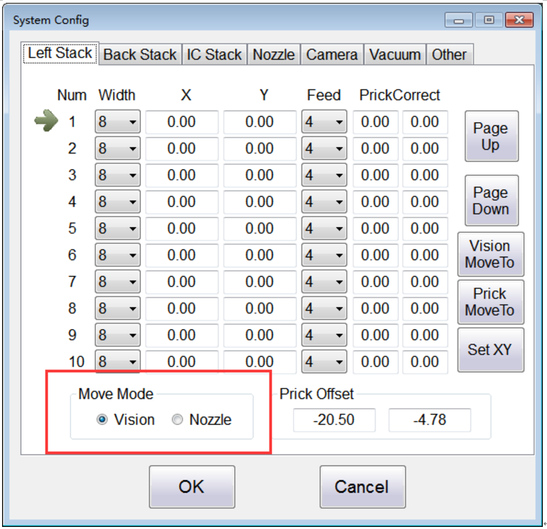
4、Add the function “ Aimed with Nozzle ” into right-click menu.
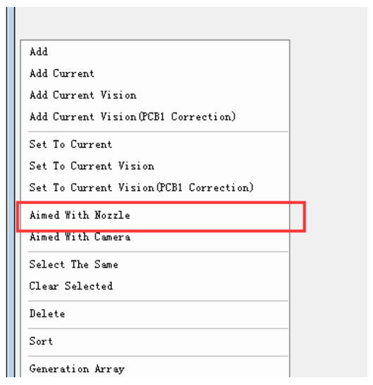
5、Optimize the way to adjust the nozzle offset better.
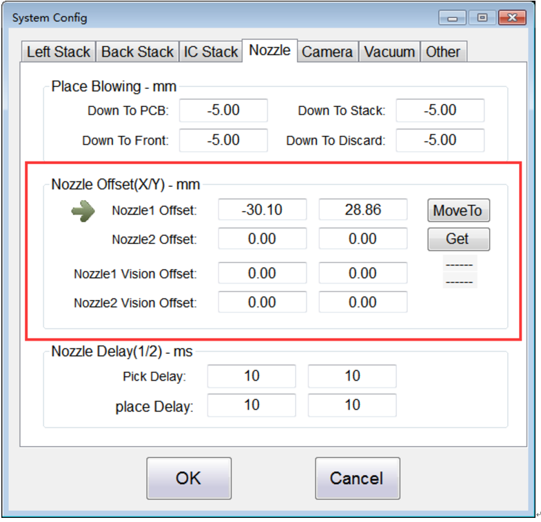
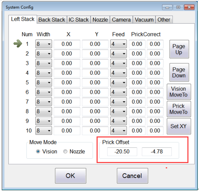
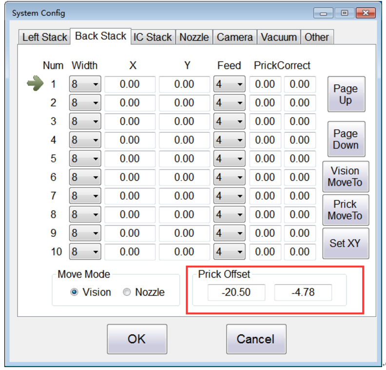
6、Change the position of the original parameters, respectively move the parameters: that “ Left Prick Offset ” and “ Back Prick Offset ”which are in the “ Other ” page to the “ Left Stack ” and “ Back Stack ” pages .
7、Optimize the data transfer protocol.
V3.01—— 2017/6/5
1、Use the down vision camera’s coordinate point for the reference point to set the any component’s point.
2、Add the “ Vacuum ” page.
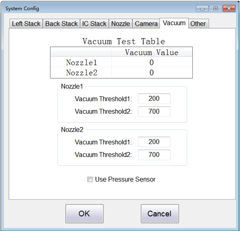
Vacuum Threshold Adjustment Description:
(1)When Vacuum Value < Vaccum Threshold1, it’s judged that the component is not sucked, and then re-suck ;
(2)When Vacuum Threshold1 < Vacuum Value < Vacuum Threshold2, it’s judged that suck component is not done well. Discard it and then re-suck;
(3)When Vacuum Value > Vaccum Threshold2, it’s judged that suck component is done well and continue run .
3、Delete the parameters:“Exposure”、“Place Blowing”、“Serial Number”.
4、Add one new algorithm that when place two components together through quick vision,take two pictures first and then deal with the data together.
5、Change the driver of the new camera.
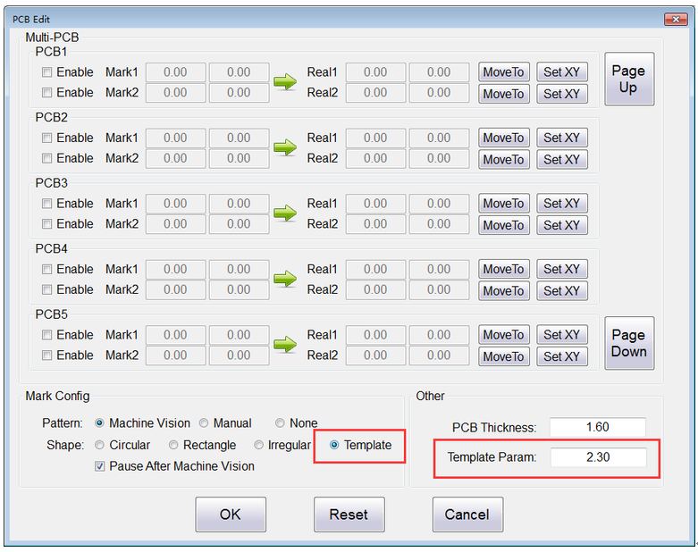
6、Add one new algorithm for the recognition function of mark point :“Template”.And add the parameter : “Template Param”.
7、When open the Vacuum 2 min,the buzzer will alarm and then turn off it.
8、When a file is placed 5 times,the machine will go home automatically.
9、Add a parameter : “Is Use AutoSort”.
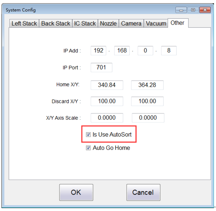
It’s a switch whether to use this function.
10、Add the function that can drag each line in the component information table.
11、The bottom layer adds the new algorithm about “S acceleration”,it can increase the speed overall.
12、Modify the BUG that the “Home X/Y” can not save.
WHAT IS SMT pick and place machine?
SMT (Surface Mounted Technology) is a comprehensive system engineering technology, which covers substrates, design, equipment, components, assembly processes, production accessories and management. When it comes to SMT pick and place machines, the automatic SMT production line requires automatic loading and unloading machine, automatic solder paste printing machine, placement machine, reflow soldering machine, AOI inspection equipment, connecting table, etc. For these SMT assembly line equipment, Qihe SMT can offer you machines in prototype SMT line, small SMT production line, mass production SMT line at low SMT line cost. Contact us now if you are interested.
WHAT IS SMT ASSEMBLY LINE?
With the development of technology, future electronic products will be lighter, smaller and thinner. Traditional assembly technology can no longer meet the requirements of high-precision and high-density assembly. A new type of PCB assembly technology-SMT (Surface Mount Technology) has emerged. SMT Assembly is the use of automated machines to assemble electronic components on the surface of the circuit board. Its density, high speed, standardization and other characteristics occupies an absolute advantage in the field of circuit assembly technology. In addition, SMT assembly has a wide range of uses.


14 Comments
good day,
maybe Ican get the latest software version TVM802BX
SN -05-22-46-C2***** for the machine
OK sent to you by wetransfer, pls check email please
A TVM802A PP machine is available. Please assist us as we lack an installer to perform software installation.
OK our service manager contacted you
Hello. I bought your machine in May 2020 on *****, so far I can’t ask for the current software. Can you send me a new version?
my serial number: TVM802A SN-**-**-**-**-**-**
software version: 3.26
Thank you very much in advance.
Dear Marcin
thank you for your feedback
We have updated the software and how to install it
sent to your email
Please check your email
If you have any problems after installation, please contact us
You can also communicate directly through skype
It’s really helpful info.
I amm glad that you just shared this helpful ino with us.
Please keep us up to date like this.
Thanks for sharing.
Glad this support page helped you
I also hope that you will continue to support us
Please update your update log to include current version 3.38
Hi Dear.
Thank you for remind,
The content of the 3.38 and 3.37 versions is the same, the format has been adjusted .
whoah thi webloig is wonderful i really like reading your posts.
Stay up thhe good work! You know, lots off people aree searching roun for this info,
you can aaid them greatly.
Thank you for your support. this support blog
main purpose is to provide old customers with the convenience of updating software
Because many customers bought machines through traders before, now they can directly contact our original factory for service, which is more direct and convenient.
We have new exhibition information updated.
It shows the latest smt products
if you are interested in them
I recommend you take a look at it
Sharing the link
pls check following exhibition news update
LED expo India
https://www.qhsmt.com/2023/05/12/led-expo-mumbai-may-2023-india-qihe-tech-invitation-smt-line/
Lighting show Ningbo
https://www.qhsmt.com/2023/05/10/smt-pick-and-place-machine-lighting-exhibition-albums-and-videos-review/
Hi there, could we have the latest firmware and software updates please.
the machine we have is TVM802A with serial number 1A-25-46-C5-CA-60 at the moment is running v3.23 software.
Kind regards,
Dimitar
Okay, we’ll send it by mail